"Special Edition" - WARNING graphic turret content

vigilante398

Authorized Vendor
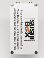
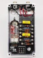
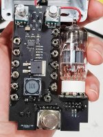
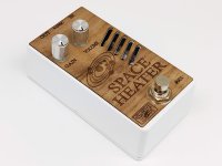
I think this is officially the first pedal build I've posted on here, but I've been building for a while. Most of my builds for the past couple years have been SMD, but all the amps I build are turretboards, so I got the idea to mix the two, and I do these as a limited run every now and then. Space Heater is a simple tube preamp, the SMD version uses 250V caps so I limit B+ to 235V, but on these I use 400V caps so I've upped B+ to 360V, and it sounds FABULOUS. I hide all the SMD stuff for the nixie-style power supply on the bottom of the board so it doesn't detract from the "mojo". CNC milling, powdercoating, and laser engraving/cutting of the faceplate were done by me in my garage, UV printing on the bottom plate was done by me in my basement. SMD soldering is a mix of pick-and-place and hand-soldering as the board house ran out of some of the components I need for the nixie supply.

Happy to answer any questions :)
IMG_20211229_233807__01.jpg
IMG_20211229_234119__01.jpg
IMG_20211229_233827__01.jpg
IMG_20211229_233625__01.jpg
 
That looks awesome! I just ordered some turrets a couple days ago. Are those pressed in or just soldered in place?

What UV printer do you have?
 
Best of both worlds. I really enjoyed building with turrets. I know G0rva has a pcb/turret board in the works. I’d imagine there is a market for those hybrid type builds. *hint hint Mr. Peadlpcb, But I’m sure you are already on it.
 
That looks awesome! I just ordered some turrets a couple days ago. Are those pressed in or just soldered in place?

What UV printer do you have?
These are just soldered in place, I don't really like dealing with staking them in. No reason you can't do either or both, but soldering takes less time than staking.

The price went up a little since I bought mine last year, but I have this printer: https://www.ebay.com/itm/193147839519 Not as high quality as the one Tayda uses (theirs is like $20k), doesn't have the clear printing option (though it does have two white ink tanks so one could theoretically be used for clear), and the software is clunky, but I get pretty good results with it.
 
Nice! I've looked at those (and similar) but wasn't too sure how the results would turn out.

Looks more than usable to me.
 
Are those pressed in or just soldered in place?
It looks like he's soldering the turrets to eyelets (correct me if I'm wrong there). Typically you can make a stake press with a couple large diameter bolts. Drill one out to receive the turret and the other grind to a point to flare the turret end around the board. You would fasten the receiving bolt with a nut and washer to a scrap of wood and chuck the ground bolt into your drill press and just press them in that way. But you can just as easily hammer them in with a blunt centerpunch on your workbench too.
 
It looks like he's soldering the turrets to eyelets (correct me if I'm wrong there). Typically you can make a stake press with a couple large diameter bolts. Drill one out to receive the turret and the other grind to a point to flare the turret end around the board. You would fasten the receiving bolt with a nut and washer to a scrap of wood and chuck the ground bolt into your drill press and just press them in that way. But you can just as easily hammer them in with a blunt centerpunch on your workbench too.
Nope, soldering turrets to eyelets would just be silly. The turrets are soldered directly to the PCB pads that I sized specifically for the job. I'm not saying installing turrets is difficult, and I have all the tools to do it, but where an electrical connection needs to be made between the turret and the PCB it makes a lot more sense to just solder them.
 
Nope, soldering turrets to eyelets would just be silly. The turrets are soldered directly to the PCB pads that I sized specifically for the job. I'm not saying installing turrets is difficult, and I have all the tools to do it, but where an electrical connection needs to be made between the turret and the PCB it makes a lot more sense to just solder them.
Ok, but that would mean that you are soldering the turrets to something that was installed in the G10 (or whatever turret board you used) in the first place, something that can receive solder. If he's building a PCB board with huge PCB pads to receive the turrets then recommending he solder it makes sense. But if he's just going to use some sort of Garolite material then, well, obviously that's a nonstarter.

If you are just a DIY guy who doesn't have the ability to make custom PCB boards then here's a pretty good explainer on how to stake them.

Like I said, a blunt centerpunch and a bench vice will also do the trick.
 
Man, wicked cool! I've been considering a project with a tube. Got a pretty cool Maxon tube driver...but want to build my own just for kicks.
 
BTW, did you design the circuit? Would you mind sharing the schematics? How do you get 360V, a charge pump?
Yup, circuit is my design. I'm on my phone right now but I'll post schematics when I'm back at the computer. The 360V comes from a "nixie-style" switch-mode power supply (SMPS) that I can't take design credit for as it's been around for a long time.
 
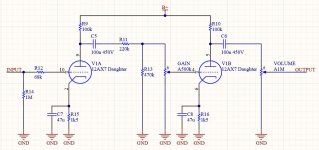
Mmkay, here's the schematics. This is the simplest preamp pedal I make, there really isn't much to it. A quick note, the tube pin numbers will look weird to anyone familiar with tubes as I use a daughter board for the tube, so the pin numbers correspond to the daughter board pinout, not the tube itself.

preamp.JPG
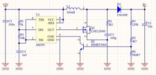
And this is the schematic of the power supply. The resistor marked 560R* is the one I adjust to change the B+ voltage, 560R gives you right around 235V, for the full 360V you need to drop it to about 360R. The part names here are the SMD versions I get pick-and-placed, it's more common to use IRF740 for the power MOSFET and UF4007 for the rectifier.

SMPS.JPG
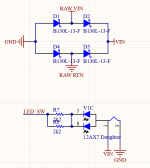
The tube mounts to a daughter board I designed that also holds the LED. I used to mount it under the tube socket, but it's way harder to service if an LED goes bad so I eventually moved the LED behind the tube. I feed the tube heater in series right off the 9V input; the tube expects 12V in series, but 9V is plenty to get it warmed up enough to pass current. Also saves you a few mA of current on the heater draw. For polarity protection I like to use a schottkey bridge rectifier on the input, so no matter what polarity the input is it will work. I use the schottkeys over standard rectifiers so the voltage drop is negligible.

1640916973290.png

I think that's pretty much it, happy to answer any other questions :)
 
Not as much of an issue since this is DC (and schottky diodes), but that bridge rectifier offsets your circuits ground potential with respect to the power supply ground. If it weren't for that (or if you had some form of isolation on the DC input) you could power the circuit on either polarity or AC.

This used to cause shocks and fireworks back before televisions/VCRs/tuners had an internal SMPS. Folks (or the antenna / cable guy) would crank down the coax cable on the back of the TV using pliers, this twisted the RF isolation block around inside the TV and shorted hot/cold ground together leaving everything external at 60-120V potential. Now take that cable and walk over and touch it to some other device that happened to be grounded (like an aerial tuner or satellite receiver) or even worse, the old two-prong polarized AC cord was shoved into the outlet the wrong way. :oops:

If you know you know, and won't likely forget any time soon. :ROFLMAO:
 
Last edited by a moderator:
Not as much of an issue since this is DC (and schottky diodes), but that bridge rectifier offsets your circuits ground potential with respect to the power supply ground. If it weren't for that (or if you had some form of isolation on the DC input) you could power the circuit on either polarity or AC.

This used to cause shocks and fireworks back before televisions/VCRs/tuners had an internal SMPS. Folks (or the antenna / cable guy) would crank down the coax cable on the back of the TV using pliers, this twisted the RF isolation block around inside the TV and shorted hot/cold ground together leaving everything external at 60-120V potential. Now take that cable and walk over and touch it to some other device that happened to be grounded (like an aerial tuner or satellite receiver) or even worse, the old two-prong polarized AC cord was shoved into the outlet the wrong way. :oops:

If you know you know, and won't likely forget any time soon. :ROFLMAO:
Yup, that was something I tested when I first started doing this, and because the difference is on the magnitude of millivolts there isn't any noticeable issue when daisy chained with other pedals.

I mainly started doing it because tube pedals pull a lot more current than typical pedals so I was having customers grab any old power supply to plug in and fry the pedals. Since I don't like saying "you have to use this power supply" this seemed like a quick and easy way to be able to say "use any power supply you want as long as its voltage is less than the input cap (16V) and it has enough current." There was some Australian company that did it on their pedals a few years back, can't remember the name, but I always thought it was a neat idea.
 
Back
Top