Spirit Box Reverb Chip Placement

I'm starting Spirit Box now that I have my parts. I got the reverb BTDR-2H LONG from stopmboxparts (love that site).
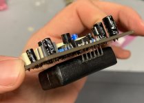
The reverb chip has 6 pins on it going 6 5 4 3 2 1 left to right when looking at the top of it. I looked up the datasheet of it and see the "pinout" is:

1. +5V
2. Power GND
3. Input
4. Signal GND
5. Output 2
6. Output 1

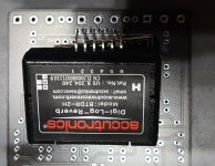
When looking at the PCB itself, the chip goes here:

1631542150202.png


Does the SQUARE PAD just above and to the right of D100 mean HOT aka that is where the reverb chip OUTPUT 1 or PIN 1 goes? Or does +5V PIN 6 go there?


Here then is the schematic portion which presumably shows the same pins 6 5 4 3 2 1 of the reverb chip. I can see clearly that PIN 4 has the Ground symbol but I am not sure what the --() means for pin 6? The way I see it, there are 4 ways this reverb chip can physically go into the PCB.

1631542296301.png
 
I was hoping to figure out where / how it mounts based on pinout and schematic instead of square peg/round hole. =) So the reverb brick goes on the bottom of the PCB. That would put PIN1 +5V of the reverb brick into the SQUARE pad on PCB which goes to the + side of the C6 10u cap? so totally backwards and upside down, basically.
 
If you turn the board over, wont the square pad be on the left, aligning with pin 6?
 
If you turn the board over, wont the square pad be on the left, aligning with pin 6?
No, sir. It would have to go in like this (I assume). Basically backwards and "upside down"... Putting the PIN 1 into the square pad. Here is a pic with chip and bottom/solder side of the PCB. Putting it in the other way, with pin 6 going to the square pad, the chip would run into the pot just above it.
 

Attachments

  • IMG_20210913_100603.jpg
    IMG_20210913_100603.jpg
    546.5 KB · Views: 32
  • Like
Reactions: fig
It works as shown in the picture. That's how mine is mounted. I made sure the solder tits were trimmed tight.
 
That is correct. It is literally the only way it will fit once components are installed. The build doc image has an outline of where it sits.
 
  • Like
Reactions: fig
It's possible to socket it with a little creativity


Robert
 
Build complete, sounds very cool this thing. I have the second two knobs OFF and teh first knob just B A R E L Y on.

there is a drop in volume when the pedal is engaged. what can I do/change to boost that output a bit from the pedal?
 
ok i swapped the R4 from 10K to 18K and that totally fixed the volume issue! cool. i didnt do anything else.
i woudl HIGHLY recommedn anyone makng sprit box to change R4 to an 18K. with the stock 10K in there, 5-7% volume drop when pedal was egnagd, no bueno.

FIXED NOW THOUGH!
 
  • Like
Reactions: fig
Here is my build. Sounds great and trust me that R4 to 18K is a MUST DO. There was a super lame drop in volume with the 10K there.
I leave the dwell and depth all the way off and I BARELY have the mix knob up.. i just like a tiny smidge of verb. this thing gest wet as hell so I have it only like 3% !
 

Attachments

  • IMG_20210914_114249.jpg
    IMG_20210914_114249.jpg
    716.1 KB · Views: 13
  • Like
Reactions: fig
OK to use a 20K for R4? It appears 18K is literally the only value resistor I don’t have on hand. Funny that. Hilarious!
 
OK to use a 20K for R4? It appears 18K is literally the only value resistor I don’t have on hand. Funny that. Hilarious!
I’ve seen people use anywhere from 15k to 20k. Could always socket it but i think it might be better to go lower rather than higher (than 18k) to try
 
Here’s mine. I almost got rid of it because I have a slo but there’s something about it that makes me keep it on the board. With distortion it’s really great. Just works better than most verbs. It’s like a spring verb but with some added drone. I did the dwell mod to the middle pot from fuzzdog. If you dime the dwell pot and turn up depth to about 11 the oscillation kinda runs away from you. It’s a little chaotic but really neat if you can tame it.
 

Attachments

  • 89A56F4A-67CE-4A30-922E-92A6C4EFB073.jpeg
    89A56F4A-67CE-4A30-922E-92A6C4EFB073.jpeg
    913.7 KB · Views: 13
  • B45BF618-BDBC-402A-B818-82746499D5DD.jpeg
    B45BF618-BDBC-402A-B818-82746499D5DD.jpeg
    1.9 MB · Views: 12
Back
Top