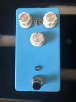
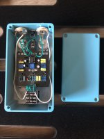
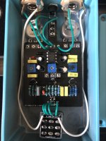
This is my third PedalPCB build and the first where I didn't have to come to the forums for help. I just plugged it in and it worked! I love the sound of it, it is definitely going to replace the Son of Ben on my pedalboard as my low wattage amp-in-a-box pedal. I think I may swap the knobs for aged white MXR style knobs but other than that I am happy with how it turned out.
Notes:
Here is the drill template I made for Tayda kits: https://drill.taydakits.com/box-designs/new?public_key=OXhWY2t1NWg1azVHYVB5a3BJMUMrZz09Cg==
It assumes a 3mm led in a bezel like mine, so you might want to adjust hole 2 depending on your preferences.
Also the build guide doesn't specify but the goal of the trim pots is to get a reading of 9V on your multimeter between the drain of each transistor and the negative terminal on the power jack. From what I understand the higher the voltage readings the more headroom the pedal will have.


