mkstewartesq
Well-known member
Sorry for what is an incredibly basic question, but this is how we learn.
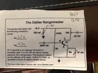
I’m about to start a Rangefinder build and, based on building a similar rangemaster clone before, I know I will need to bias at the very end to try to get to 7 V. My super basic question is how exactly do I do that with a multimeter? I understand that the positive lead is going to be measuring at the Collector of the transistor– but what am I doing with/where am I placing the black lead?
The one rangemaster clone I built before was an Aion kit, excellent for beginners, so that board simply had two test pads to which you touch the multimeter leads to do the biasing. So I’ve never really done a true “manual” biasing before. And every YouTube video I found always has the person doing the test say “and of course the other side is connected negative“ or the “other side is connected to ground” but they never actually show that connection in the video (It’s always obscured or offscreen).
Thanks in advance.