Super Hetrodyne Receiver burning resistor

quazimoto

New member
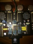
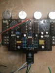
Greetings! Just finished this up yesterday and immediately I start to smell something during the trial run before boxing up. After further inspection it was a 10 ohm resistor just to the right of the TL072 OP Amp. The connection closest to the op amp has continuity with ground. I checked the board over with a jewelers lope to see if there was any solder bridges or something else touching and could not find anything. All the op amp pins are socketed and not touching anything. Any ideas? I don't believe this one had a schematic.
339
340
341
 
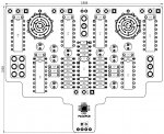
It is tough to troubleshoot a board without a circuit schematic, and I don't even see a picture or this PCB with the part values on it in the build documents. Were you filling the board with parts using the part values printed on the pcb? Did you take a picture of the empty PCB to use for reference since the parts mostly cover up the values printed on the PBC? Ordinarily you would not need to do that because you would have a build document to use for reference, but when you don't have it you need to take extra precautions in case something does not work when you get the board put together.

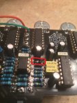
The part you circled in the picture looks like a diode instead of a resistor. You should make sure you have the right part in that spot. The holes on the left side of that diode that you circled, and the 3rd resistor below it (the one above the white box capacitor), look like they need more solder. You should first make sure you have the diode correctly placed in the board before you add any more solder to it, and while you are at it check the orientation on all the other diodes and electrolytic capacitors on the PCB.

Note that even if your part like the diode looks on the other side of the PCB like it is soldered in OK, if the board is not working and you see empty hole space around the leads on the other side, it is a good idea to flow enough solder to that connection to fill that empty space. Sometimes there are separate traces on both sides of a PCB that need to connect to a part. Take a close look at your other resistors on the board and touch-up the solder to make sure you are filling in the holes where the leads connect to the PCB.
 
The burned resistor appears to be R11. Aside from the obvious, like a solder bridge or a pot touching the back of the PCB, it could be any one of the IC's shorted causing the problem.

First make sure you've installed them all in the correct locations.

Use your DMM to measure resistance to ground on the left pad of the burned resistor, you'll likely measure a short (low ohms).

Remove the ICs one at a time until the short goes away. If it does, then you have located the defective IC.

If the short doesn't go away after removing all of the ICs then you have a solder bridge or something making contact where it shouldn't somewhere in the circuit.


342 343
 
It is tough to troubleshoot a board without a circuit schematic, and I don't even see a picture or this PCB with the part values on it in the build documents. Were you filling the board with parts using the part values printed on the pcb? Did you take a picture of the empty PCB to use for reference since the parts mostly cover up the values printed on the PBC? Ordinarily you would not need to do that because you would have a build document to use for reference, but when you don't have it you need to take extra precautions in case something does not work when you get the board put together.

The part you circled in the picture looks like a diode instead of a resistor. You should make sure you have the right part in that spot. The holes on the left side of that diode that you circled, and the 3rd resistor below it (the one above the white box capacitor), look like they need more solder. You should first make sure you have the diode correctly placed in the board before you add any more solder to it, and while you are at it check the orientation on all the other diodes and electrolytic capacitors on the PCB.

Note that even if your part like the diode looks on the other side of the PCB like it is soldered in OK, if the board is not working and you see empty hole space around the leads on the other side, it is a good idea to flow enough solder to that connection to fill that empty space. Sometimes there are separate traces on both sides of a PCB that need to connect to a part. Take a close look at your other resistors on the board and touch-up the solder to make sure you are filling in the holes where the leads connect to the PCB.
It does have the drill template and parts list on the store site. That is what color the resistor turned when it burnt. Definitely not a diode! I will go back and reflow some more solder as you suggested. Thank you!
 
The burned resistor appears to be R11. Aside from the obvious, like a solder bridge or a pot touching the back of the PCB, it could be any one of the IC's shorted causing the problem.

First make sure you've installed them all in the correct locations.

Use your DMM to measure resistance to ground on the left pad of the burned resistor, you'll likely measure a short (low ohms).

Remove the ICs one at a time until the short goes away. If it does, then you have located the defective IC.

If the short doesn't go away after removing all of the ICs then you have a solder bridge or something making contact where it shouldn't somewhere in the circuit.


View attachment 342View attachment 343
Will do! Thank you sir!
 
Back
Top