Grubb
Well-known member
I'm playing around with the Six String Stinger circuit at the moment, planning out a few potential mods. Having learned this week that this OD/boost pedal has absolutely nothing to do with a very clean high headroom boutique tube amplifier - which is obvious on reflection - and is instead built on the platform of Jack Orman's Minibooster, I am thinking through what I can tinker with to get different sounds out of the circuit. One of the ideas I'm considering is to increase the level of overdrive by decreasing the value of the source resistors on each miniboost stage (there are two in the pedal). Orman's original design had the value at 100R, with 1K as a suggested value for mild overdrive. Meanwhile the stock value on the Vertex unit (which is a slightly gritty boost) is 10K.
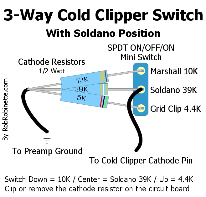
I intend to trial a few values and put my preferred settings on a switch. It seems easy to swap between two resistor values on each source resistor using a DPDT switch. Is it possible to switch between 3? I had in mind the King of Tone switching that can easily be set up to toggle between Boost, OD and distortion, but that's opening and closing diode clipping circuits rather than toggling between component values. I can't at this moment apprehend how to do it in the context of the Stinger:

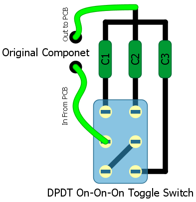
I've just used SPDT switches in this mockup, as I try and work out how to do it. I haven't attempted to connect the switch on the right side of the diagram yet, just to preempt any smart Alecs Please feel free to point out any areas of misunderstanding you can identify. Can I hook up all 3 resistors?
- and is instead built on the platform of Jack Orman's Minibooster, I am thinking through what I can tinker with to get different sounds out of the circuit. One of the ideas I'm considering is to increase the level of overdrive by decreasing the value of the source resistors on each miniboost stage (there are two in the pedal). Orman's original design had the value at 100R, with 1K as a suggested value for mild overdrive. Meanwhile the stock value on the Vertex unit (which is a slightly gritty boost) is 10K.I intend to trial a few values and put my preferred settings on a switch. It seems easy to swap between two resistor values on each source resistor using a DPDT switch. Is it possible to switch between 3? I had in mind the King of Tone switching that can easily be set up to toggle between Boost, OD and distortion, but that's opening and closing diode clipping circuits rather than toggling between component values. I can't at this moment apprehend how to do it in the context of the Stinger:
I've just used SPDT switches in this mockup, as I try and work out how to do it. I haven't attempted to connect the switch on the right side of the diagram yet, just to preempt any smart Alecs
Please feel free to point out any areas of misunderstanding you can identify. Can I hook up all 3 resistors?