TC Nova Delay ND-1

I picked up a known non-working TC ND-1 Nova Delay. It powers on but there is no sound. Do we discuss t-shooting non PedalPCB stuff here? Looking for some tips/pointers as to where to begin the t-shooting process to see if I can make this pedal work, else I will have to sell it for very cheap.
 
We'd be more than happy to help! Share some pics of the pedal and a schematic otherwise we cannot help much. One of the first things to do is simply look at the board. Does everything appear to be soldered correctly? Use your DMM to test voltages at any opamp or transistor and post them here.

Use an audio probe and follow along with the schematic. Start at the input/output and work your way forward/backward.
 
The first thing I did was google for schematic but they do not appear to exist. TC seems to have never published them or just never made them available to public.
I have the unit open and there are 2 PCB's. One has the tap tempo/on off and LED readout, the second is the main PCB. I looked over with fine tooth comb and do not see anything OBVIOUS. The tiny little fusable link is good which makes sense becuase the unit does power on, it just does not output any sound and does not respond to the tap tempo button. I'm afraid it's one of the SMD based components or the DSP or any such component like that which would be very hard to source. Here are pics of top and bottom..
 

Attachments

  • IMG_20210830_071903.jpg
    IMG_20210830_071903.jpg
    1.3 MB · Views: 19
  • IMG_20210830_071921.jpg
    IMG_20210830_071921.jpg
    1.2 MB · Views: 19
Hmm. I would google the pinouts of all the ICs and the 7805 (the bent one on the left with the hole) and check all the power points. Power is usually my first place to check based on experience. I'm not that skilled in tracing a PCB to schematic yet so I'll have to defer to someone else.
 
I picked up a known non-working TC ND-1 Nova Delay. It powers on but there is no sound. Do we discuss t-shooting non PedalPCB stuff here? Looking for some tips/pointers as to where to begin the t-shooting process to see if I can make this pedal work, else I will have to sell it for very cheap.
TC Electronics are notororious for the dodgy Footswitch/ Soft Switch!
Give it a Good spray of Electrical Cleaner as it may be the culprit!
 
I think the tap tempo footswitch button is just a secondary issue... the main issue is the zero output of sound. well, actually it makes sound IF i max out all of the knobs and make it do an endless delay feedback on itself but its super faint, quite as a mouse and barely audible.

googled the pin outs of the 7805CT.

1630334169383.png


SO with power to the unit, check those 3 pings looking for .033uF GND .01uF?
 
Begin at the beginning.
Given you don't have a schematic, it makes most sense to me to start the audio trace at the input, rather than working your way back from the output.

I'd start with music6000's suggestion, then BuddytheReow's suggestions of taking an audio probe to it first, in conjunction with DMM set to continuity beep-mode and start roughing up your own schematic.

I got a ton of great help trouble-shooting an Electric Mistress here. I try my best to pay it forward, but alas I'm no EE and not very good at troubleshooting...
 
I
I think the tap tempo footswitch button is just a secondary issue... the main issue is the zero output of sound. well, actually it makes sound IF i max out all of the knobs and make it do an endless delay feedback on itself but its super faint, quite as a mouse and barely audible.

googled the pin outs of the 7805CT.

View attachment 15445


SO with power to the unit, check those 3 pings looking for .033uF GND .01uF?
I was referring to the Soft switches in general, ON/ OFF & Tap Tempo.
 
I measured 7805CT With DMM set to DC I get this:
PIN 3 5V
PIN 2 nada
PIN 3 10.8V

With my DMM set to "auto sense" I get this:
PIN 3 0
PIN 2 0
PIN 1 9 MEGA OHMS

I will have to build an audio probe. A nice member on the forum sent me a pdf guide on how to make one with
100nF (.1uF) Capacitor, preferably ceramic disc type, as it is likely to be small. 16-100V rating is fine.
• A few feet of stranded wire, preferably 2 colours such as red and black or red and green. Gauge is not
critical, but we'll say in the 18-24 gauge range is fine.
• A female 1/4 inch diameter Audio jack that is designed to be soldered onto the end of a wire; not the
type that mounts into an enclosure
 
This is what it would look like. Drew it real quick with TinyCAD
1630335335203.png

The jack you use doesn't really matter as long as you can solder 2 wires to it: ground and the actual signal (marked tip). That goes to a capacitor. The capacitor should be roughly 100n and I used a box film one. It's purpose is to filter our all unwanted DC in the signal (you guitar sends AC signal). The other unused lead of the capacitor is your audio probe or you can solder a wire to that to make it a bit easier for testing.
 
I have built my probe using a 100n box film cap. I have the alligator clip on ground of circuit and my probe lead is hovering. i have the INPUT of my probe coming from a guitar (for now) and then I have the output of the delay going to a crappy amp. I strum gutiar and start placing probe onto the ND-1 trying to get output and so far guessing all the way along, zero output.

EDIT: PROBE is working. I touched the probe lead to the second lug down on the output jack (the black cable you see below is plugged into the LEFT MONO OUTPUT of the delay) and I can hear my strummed guitar coming thru my crappy amp. This of course proves nothing other than the probe works since all I am doing is sending the output... to the output.
 

Attachments

  • IMG_20210830_092136.jpg
    IMG_20210830_092136.jpg
    1.2 MB · Views: 5
Last edited:
IMO It may be easier to do it the other way around with the probe jack connected to your amp and your guitar going into the normal jack of the pedal. Test the input jack first with your probe to make sure that's not the culprit. If it is you've saved yourself potentially hours lol.

The pinouts of the various opamps will tell you where to put your probe. They're usually marked output.
 
My probe was built with an Ibanez barrel jack, an alligator clip, a 100n BF cap and a random wire/clip lead I had. The probe lead is not set to go as 1/4" output to an amp.

This is very interesting. What I did was take a 1/4" to 1/4" stubby jack (like the ones to connect pedals). I have that into INPUT LEFT. When I strum my guitar and touch my probe to tip. I GET PROCESSED SOUND!

If I touch my probe to the OUTPUT of the OPAMP 7805CT PIN 3 i do not get any sound.
 

Attachments

  • IMG_20210830_094024.jpg
    IMG_20210830_094024.jpg
    813.8 KB · Views: 5
Last edited:
OK so here is some interesting stuff. I have the PROBE clipped to ground and i have the probe female 1/4" output sending singal to my crappy amp.
I have a DRUM MACHINE plugged into input LEFT and when I touch my PROB to the output jack it sounds NORMAL.

when i touch my probe to the output of the OP AMP called 7805CT it is very faint and sounds like ass. do i have a bad op amp and should I look for a 7805CT in the same physical layout and give it a go? the voltages are good at the op amp.
 
the 7805 is merely a voltage regulator to power a different IC correctly. No guitar signal goes through that. Your voltages for it above look good: Output (5v) Ground (0v as it should be) and Input (10v but can't confirm with out schematics). No need to test this further
 
So what do you make of THIS. Instead of strumming a guitar as my audio source (and wanting both hands free) I plugged in my old as hell Zoom drum machine and had a bass line going. This worked great to test and get output. I did not pay attention to what the output level was on the machine etc, but it worked fine and the delay pedal seemed to be normal.

I button the pedal back up, put the pedal on my board and into the FX loop..... back to no sound/barely freaking audible.. I pull it off the board, put it back on the bench, plug in drum machine. works great.

What is this tell tale sign of? Some kind of input resistor and the pedal only working if it sees a really hot line signal?

EDIT - Took it back apart, still using drum machine but turned volume way down on drum machine. The issue is V E R Y low output. When I probe the actual output jacks VERY VERY low output, however, when I put my probe on top of C135 or C134, nice big fat output. I also see a few IC in this area, IC8 and IC15. when I probe those, big fat output if i probe what I would call pin3 or pin8. i so badly want to fix this but I do not know how. crazy thought to wire C135 or C134 directly to the dang output jack.
 
Last edited:
You're saying when you put a looper pedal/drum machine into the input the pedal works just fine, but regular guitar signal once you boxed it back up barely works? Forgive me for saying this, but is your guitar volume knob up all the way? No offense, but I've done this more that you think.

Try putting a booster before it if that does anything
 
LOL! Trust me, it is NOT the guitar pot. It is EXTREMELY LOW OUTPUT from the delay pedal. The only reason I was getting any sound at all with the drum machine is because the drum machine was CRANKED. I am realizing now the OUTPUT level from the OUTPUT jack is about 95% less than it should be, regardless of drum machine or a bass or a very hot guitar, etc. If I set the probe on top of C135 or C134 or on 2 of the pins of IC15 or IC8 it is very fat and fully wet signal volume and what should be coming from the output jacks. So there is a break somewhere between input and output. The question is, where is the break. I cannot find a schematic so I randomly starting putting my test probe on everything and that is when I discovered very nice loud, processed output at those 2 caps and 2 IC's.

Can i jumper directly from those 2 capacitors to the outputs lugs? I have to assume one is Left and one is Right.
 
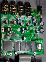
Are C134/C135 close to the L/R output jacks?
What are the two large grey box caps next to the jacks connected to?

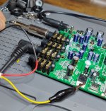
Using your DMM set to continuity-beep mode, put the DMM's negative probe on one side of C134 and using the DMM's hot probe, find every other component that's connected to C135 on that one side. Then do the same for the other side of C134.

Repeat the DMM continuity process for C135, both sides, making note of anything connected to it.


Couple things to point out:
1) Just because a cap has a high number doesn't mean it's near the output (and low number near the input such as C1 or C2) — schematic numbering goes however the person drew up the schematic wants, and if they started with the power section for numbering that's where you'll find C1, C2, etc.

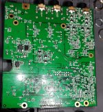
2) Just because a component is located physically on one side of the board doesn't mean it's not connected electrically via a trace to the complete opposite side of the board. Keep that in mind while checking for continuity with your DMM.

So that said, jumpering from C134 and C135 direct to the output jacks may work, but may take a number of important stages of the circuit out of the equation, such as you get dry signal at the output, but maybe not the delayed signal or vice versa. Go ahead and temporarily jumper them, see what you get.

As I said, start at the BEGINNING, because as BuddytheReow said — doing so will save you potentially hours of trouble shooting. However, since you've now already established that you get signal as far as C134 and C135, continue from there — Be systematic, that's key.

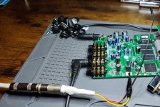
Find what's connected to C135 and C135 and then audio probe those connected components. DMM-continuity check those newly-found connected components to see what they in turn are connected to — keep spreading out your web of connections, remember that just 'cause it's connected doesn't mean it's part of the audio path, so don't be duped into thinking you've found the disconnect at a point where the audio-path disappears. Keep checking continuity and audio-probing.


At least, that's how I would approach this.
 
Back
Top