BuddytheReow
Breadboard Baker
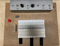
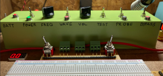
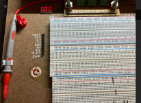
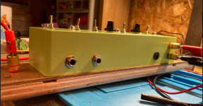
For those of you not really that interested or TL/DR, this is just a breadboarding platform that came out of my head and inspired by PedalPCB's Protoboard.
Now, for the fuller story.
I had a Protoboard since about last summer around around the time the Test Kitchen finally opened up here. Originally, I was breadboarding on a few pieces of cardboard duct taped together. Take a look at my older Buddy's Breadboard posts and you'll see what I mean. Once the Protoboard arrive it was a definite upgrade from what I had. Multiple voltages, pot mounting hardware, all offboard wiring fully integrated, etc. But, it was still a breadboard once all was said and done. You have to enjoy breadboarding to appreciate the Protoboard. If breadboarding is not your thing, that's cool; more people here would rather solder than breadboard when given a choice. For me, breadboarding accomplished a few things: it's a way for me to try a circuit out before committing to solder, experiment with any particular mods I may have seen out there, going back to basics and figuring out how a certain part works, or just throwing some circuit Legos on there and see what happens.
For the record, I'm not here to bash the Protoboard in any way, shape, or form. I think it's a great product, very compact, and ticks a lot of the basic needs for guitar circuit nerds out there. The protoboard IMO has a few flaws or maybe I should call them gaps in the design. Many times when I've tested and played through a circuit and decide to wrap it up for the day I sometime forget to turn the darned thing off. If a battery was hooked up to it then you'll probably have a dead or close to dying battery by the next day. I think a LED indicator should be mounted on it next to the main power switch. After I've spent a considerable amount of time putting a circuit together I'll walk over to my amp, plug in a guitar, and hear just a clean signal come through. A LED indicator should be on the Active/Bypass switch as well to make it more idiot proof. Or at least Buddy proof, lol.
Third. For my own personal reasons and due to the layout of my basement, I wanted the Protoboard to have a test function. Many times I'll think I've completed a circuit, get up off my chair, pick up my board, walk it over to the amp, plug the amp in, plug the guitar in, turn the amp on, sling the guitar around my neck, turn the volume on my guitar up, engage the power switch, engage the bypass switch, and then I'll hear nothing. What? I thought everything looked good just a minute ago. Ugh. Let me take it back to the bench and figure out what's going on. What I SHOULD have on my bench is a cable to connect to my phone or something just to put some signal into the circuit just to check that it's alive. But sadly I don't. So, a needed feature for the Protoboard IMO is a simple wave generator just to throw a signal of some kind with the ability to alter the frequency and volume.
Fourth. It's inevitable when breadboarding or even soldering up a PCB that you'll need to take the time to troubleshoot. Is everything getting power that should be getting power? Where is my audio signal dying in the circuit? The workaround for the former is to take out a DMM, hook the black lead up to ground, engage the power, then start poking away. The audio probe can be solved simply by taking the output jumper and touching it on the part in question. This also means you should have some kind of signal going through the input. See point number 3 again.
Fifth. When I breadboard a circuit from a schematic, I work from left to right with the left side the input section and the right side the output section. The protoboard has all the 'plug and play' features on the left hand side which is fine 98% of the time. The problem for me is when I have to reach all the way over with a jumper wire to the edge of my breadboard and sometimes bends or knocks a component out. Not Earth shattering, but annoying at times. For me, I think the output plugs should be on the right hand side of the breadboard.
Ok. Now that that's out of the way I want to talk about the story behind my project. It all started when @Chuck D. Bones posted in his boneyard forum a Mini Tube Circuit. This really piqued my interest simply because I can play around with certain tubes at a non-lethal voltage level, but they require more than 18V which is the max that the protoboard can provide. I think Chuck and Fig were both using a bench supply at the time when messing around with this circuit. Call it FOMO, but I wanted to see what all the fuss was about and I didn't feel like pulling the trigger on a bench supply. The Mini Tube circuit uses 26V according to the schematic. This project sat on the back burner for quite some time.
About 6 weeks ago or so the itch started creeping up again to breadboard this circuit and I started looking into a bench supply to see if they were affordable and can fit on my bench. The cheap ass in me was hesitant to buy it and Fig offered to donate an extra one of his to the cause. Fig is a pretty cool dude. Fast forward about a week and I have the bench supply along with a few other goodies and am playing around with it and trying a few small circuits out. One of the goodies is a cheap LED volt meter that I thought was pretty darned cool and wanted to incorporate one on my protoboard for when I plug a battery into it to see when I need to replace it. I don't really use batteries a whole lot until I made my pedalboard. Then one day I have a shower thought of "Why don't you build your own breadboard platform?" Thus the quest began... You can read about the whole experience/process here but I'll try to sum up.
 forum.pedalpcb.com
My main problem when I pull a project out of my ass is that I usually start making before I do some real planning. My planning consisted of "how to I hook up the various switches" or "what parts do I have in my inventory to make this?" I should have been asking the more appropriate questions such as "What parts of the protoboard work and what parts do I need to work on?" or "What parts should I have in order to make this?". I have some basic woodworking tools and experience plus pedal making skills, so I knew this project would be possible. All that being said, this project went through not one, not two, but THREE different revisions. It was interesting breadboarding some of these circuits before committing to solder so I can breadboard other things... uh, what?
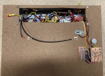
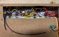
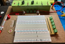
Anyways, huge should out to @fig and @Chuck D. Bones for their help on making this project possible. I'll show off the actual project below, though it still needs a paint job.
Now, for the fuller story.
I had a Protoboard since about last summer around around the time the Test Kitchen finally opened up here. Originally, I was breadboarding on a few pieces of cardboard duct taped together. Take a look at my older Buddy's Breadboard posts and you'll see what I mean. Once the Protoboard arrive it was a definite upgrade from what I had. Multiple voltages, pot mounting hardware, all offboard wiring fully integrated, etc. But, it was still a breadboard once all was said and done. You have to enjoy breadboarding to appreciate the Protoboard. If breadboarding is not your thing, that's cool; more people here would rather solder than breadboard when given a choice. For me, breadboarding accomplished a few things: it's a way for me to try a circuit out before committing to solder, experiment with any particular mods I may have seen out there, going back to basics and figuring out how a certain part works, or just throwing some circuit Legos on there and see what happens.
For the record, I'm not here to bash the Protoboard in any way, shape, or form. I think it's a great product, very compact, and ticks a lot of the basic needs for guitar circuit nerds out there. The protoboard IMO has a few flaws or maybe I should call them gaps in the design. Many times when I've tested and played through a circuit and decide to wrap it up for the day I sometime forget to turn the darned thing off. If a battery was hooked up to it then you'll probably have a dead or close to dying battery by the next day. I think a LED indicator should be mounted on it next to the main power switch. After I've spent a considerable amount of time putting a circuit together I'll walk over to my amp, plug in a guitar, and hear just a clean signal come through. A LED indicator should be on the Active/Bypass switch as well to make it more idiot proof. Or at least Buddy proof, lol.
Third. For my own personal reasons and due to the layout of my basement, I wanted the Protoboard to have a test function. Many times I'll think I've completed a circuit, get up off my chair, pick up my board, walk it over to the amp, plug the amp in, plug the guitar in, turn the amp on, sling the guitar around my neck, turn the volume on my guitar up, engage the power switch, engage the bypass switch, and then I'll hear nothing. What? I thought everything looked good just a minute ago. Ugh. Let me take it back to the bench and figure out what's going on. What I SHOULD have on my bench is a cable to connect to my phone or something just to put some signal into the circuit just to check that it's alive. But sadly I don't. So, a needed feature for the Protoboard IMO is a simple wave generator just to throw a signal of some kind with the ability to alter the frequency and volume.
Fourth. It's inevitable when breadboarding or even soldering up a PCB that you'll need to take the time to troubleshoot. Is everything getting power that should be getting power? Where is my audio signal dying in the circuit? The workaround for the former is to take out a DMM, hook the black lead up to ground, engage the power, then start poking away. The audio probe can be solved simply by taking the output jumper and touching it on the part in question. This also means you should have some kind of signal going through the input. See point number 3 again.
Fifth. When I breadboard a circuit from a schematic, I work from left to right with the left side the input section and the right side the output section. The protoboard has all the 'plug and play' features on the left hand side which is fine 98% of the time. The problem for me is when I have to reach all the way over with a jumper wire to the edge of my breadboard and sometimes bends or knocks a component out. Not Earth shattering, but annoying at times. For me, I think the output plugs should be on the right hand side of the breadboard.
Ok. Now that that's out of the way I want to talk about the story behind my project. It all started when @Chuck D. Bones posted in his boneyard forum a Mini Tube Circuit. This really piqued my interest simply because I can play around with certain tubes at a non-lethal voltage level, but they require more than 18V which is the max that the protoboard can provide. I think Chuck and Fig were both using a bench supply at the time when messing around with this circuit. Call it FOMO, but I wanted to see what all the fuss was about and I didn't feel like pulling the trigger on a bench supply. The Mini Tube circuit uses 26V according to the schematic. This project sat on the back burner for quite some time.
About 6 weeks ago or so the itch started creeping up again to breadboard this circuit and I started looking into a bench supply to see if they were affordable and can fit on my bench. The cheap ass in me was hesitant to buy it and Fig offered to donate an extra one of his to the cause. Fig is a pretty cool dude. Fast forward about a week and I have the bench supply along with a few other goodies and am playing around with it and trying a few small circuits out. One of the goodies is a cheap LED volt meter that I thought was pretty darned cool and wanted to incorporate one on my protoboard for when I plug a battery into it to see when I need to replace it. I don't really use batteries a whole lot until I made my pedalboard. Then one day I have a shower thought of "Why don't you build your own breadboard platform?" Thus the quest began... You can read about the whole experience/process here but I'll try to sum up.
Making the "Ultimate" Prototyping Breadboard - A BtR Creation
Hey Folks, I'd rather just write my thoughts down than lose sleep over this. My original breadboard was 2 breadboards mounted on a few pieces of cardboard. Then a protoboard fell into my lap last year. An excellent upgrade indeed! The protoboard is great, but I think it needs some additional...
My main problem when I pull a project out of my ass is that I usually start making before I do some real planning. My planning consisted of "how to I hook up the various switches" or "what parts do I have in my inventory to make this?" I should have been asking the more appropriate questions such as "What parts of the protoboard work and what parts do I need to work on?" or "What parts should I have in order to make this?". I have some basic woodworking tools and experience plus pedal making skills, so I knew this project would be possible. All that being said, this project went through not one, not two, but THREE different revisions. It was interesting breadboarding some of these circuits before committing to solder so I can breadboard other things... uh, what?
Anyways, huge should out to @fig and @Chuck D. Bones for their help on making this project possible. I'll show off the actual project below, though it still needs a paint job.


