Chuck D. Bones
Circuit Wizard
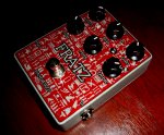
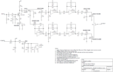
This is a 4049-based distortion, inspired by the runoffgroove Double-D. For those not familiar, the CD4049 is a CMOS hex inverter that is normally used for digital applications. Long ago some clever analog engineers figured out that this particular CMOS device (and a couple of others) can be hijacked for analog purposes. I built my first 4049-based distortion back when... well let's just say that Keith Moon was still alive. The 4049 makes a distortion sound that is unlike bipolar transistors, diodes or opamps and can be very tube-ish. These days there are quite a few boutique pedals that use the 4049, including the Bloody Finger (Chrome Dome). To make a long story even longer, I was fishing around the 'net for 4049-based distortions and came across the ROG Double-D. The 4049 contains six inverters (amplifiers) and it's a challenge to see how many can be used in one pedal before the gain and noise get out of hand. This one uses five to the six inverters, arranged as two separate distortion channels. The Jiggle channel uses two inverters, has moderate gain and a tight bottom-end. Clean boost it attainable at lower gain settings. The Bounce channel uses three inverters and is designed for high gain and maximum sustain. The ROG Double-D has four knobs: two for GAIN and two for VOLUME. Pretty simple. Maybe too simple. So I threw in four more knobs: a TONE control for each channel, a PREGAIN control for the shared JFET preamp and a BIAS control to throttle the power to the 4049. At high BIAS, the 4049 gets almost the full 9V, yielding tons of headroom and 6Vp-p max output. At low BIAS, the gain drops, the distortion is more compressed and a bit gated. Less volume is available, only 3Vp-p  . In the middle, there is a sweet-spot where the gain peaks and the tone is nicer. The TONE controls are high-cut that vary from 580Hz to 14KHz. In the ROG circuit, the JFET preamp runs at maximum gain. I added the PREGAIN control to reign it in a bit when needed. I also re-arranged the Bounce channel GAIN control to give more range and less noise. When I was first checking this out on the bench, it was motor-boating. After a couple of days of swearing, troubleshooting and more swearing, I came to the realization that the pedal was fine, it was the power supply that was oscillating. The 4049 presents a "funny" load to the power supply and this one didn't like it. It was fine with battery power or with a more stable power block.
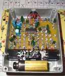
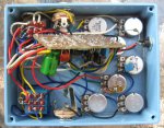
The parts count is pretty low considering how much this beast does. I socketed the 4049 because some are noisier than others.
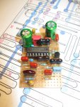
Yeah, the inside's a bit of a rat's nest. I was lucky: no squealing. The board faces down and the bottom cover has a layer of duct tape for insulation. Those resistors on the stomp switches are the ballasts for the LED rings.
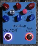
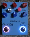
The stomp switch on the right selects the channel: red for Jiggle, blue for Bounce.
The parts count is pretty low considering how much this beast does. I socketed the 4049 because some are noisier than others.

Yeah, the inside's a bit of a rat's nest. I was lucky: no squealing. The board faces down and the bottom cover has a layer of duct tape for insulation. Those resistors on the stomp switches are the ballasts for the LED rings.

The stomp switch on the right selects the channel: red for Jiggle, blue for Bounce.


