Chuck D. Bones
Circuit Wizard
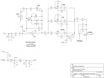
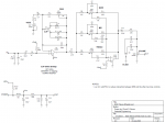
I built a version of the Chela (EQD Talons) and posted a build report. This post describes the mods in detail. The Chela schematic is available in the Build Docs, so I won't post it here. This is the schematic of my build. I kept the ref designators the same, as much as possible.

I added a CLIP switch (S2) so I could select between the original symmetric LED clipping, no clipping and asymmetric MOSFET clipping. The MOSFET clipping is about the same volume as the LED clipping, but it generates even and odd harmonics. The LED clipping generates only odd harmonics. At high GAIN settings, the two sound pretty much the same, but at lower GAIN settings, the MOSFET clipping is smoother and thicker, not as harsh as the LEDs. The "no clipping" option allows clean boost or opamp clipping, depending on the GAIN setting. I added a VOICE control as an experiment to see how it affected the tone. The VOICE control does three things:
1) It alters the range of the GAIN control.
2) It changes the bass response, in conjunction with C4.
3) It limits the current in the clipping diodes or MOSFET, affecting the harmonic content.
All three functions of the VOICE control make it very useful in tailoring the tone of this pedal. I ended up mounting the VOICE pot where the PRESENCE pot used to go.
The Talons' PRESENCE control would be more aptly named ABSENCE because it weakens the TREBLE, MID and BASS controls and does not do enough to trim off the top end. There is a need for additional high freq cut beyond what the TREBLE control can do, but the way EQD did it was not good. I jumpered R6 and the PRESENCE pot and removed C5. I initially moved the PRESENCE pot to just before the VOLUME control. I found that I only used a couple of settings, so I replaced the PRESENCE pot with a switch (S3). In the center position, there is no additional treble cut. The up and down positions provide medium and heavy treble cut, respectively. The TREBLE control's range provides overlap in the three PRESENCE switch settings. If you don't do any other mod to the Chela, you should really do the PRESENCE mod because getting rid of C5, R6 and the PRESENCE pot between IC1.1 and the tone controls makes a huge improvement in the operation of the tone controls.
I retuned the tone controls a little bit, moving the MID and TREBLE controls down in frequency about 1/2 octave and increasing the BASS pot's boost and cut range. C6 was increased to allow more bass thru. While we're on the topic of the tone controls... the MID control overlaps the BASS & TREBLE controls quite a bit. With this circuit topology, there is really no way around it. What it comes down to is the the TREBLE and BASS controls work best when MID is at noon. When MID is near the ends of its range, it overwhelms the BASS & TREBLE controls and they lose most of their adjustment range.
Lastly, I added the Charge Pump board so that I could run the board on +18V. The Chela needs the additional headroom because advancing the MID pot beyond 2:30 causes the last stage to saturate. D100 is no longer needed since the Charge Pump board provides reverse polarity protection. I replaced D100 with a 100Ω resistor for some additional power filtering. I increased R101, R102 and C101 to get more filtering on Vref. R5 now returns to ground, thru the VOICE pot, instead of to Vref. With +18V power to the board, this pedal is capable of delivering over 13Vp-p at full-tilt, so overdriving a tube amp is no problem.
C4, R5, D1, D2, Q1, C5 and C13 are mounted on a Vero board that is supported by S2 & S3. C4 and R5 could have been left on the board, but the wiring to the VOICE pot is cleaner with them mounted outboard.
I touched a few other component values; you can compare my schematic against the Chela BOM to see which parts I changed.
Last edited:


