This Week on the Breadboard: A Mini Tube Pedal

Chuck D. Bones

Circuit Wizard
About a week ago, Billy sent me the schematic for the Freeverb, a spring reverb circuit that uses a pair of 6418 vacuum tubes for some of the amplification. I was intrigued and the next day I ordered some up on eBay. The 6418 was designed to be small and very low power. The filament power is only 12.5mW. These babies don't glow or even get warm. They also work with low plate voltage.
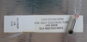
JAN6418.jpg

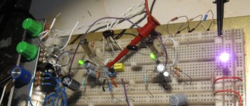
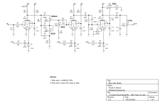
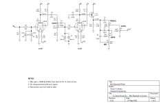
Anyway, I ginned-up this little circuit to see what's what. Total gain is about 48dB. The transistor buffer is there to keep the LEVEL control from loading V2. It works fine without Q1, the gain is just 6dB lower. The 6418 is a directly-heated tetrode. There are a pair of deflector plates connected to the filament that steer the electron flow toward the anode (plate) on pin 1. This circuit makes a fair amount of clean boost before the 2nd harmonic starts to show up. Max clean output is 5Vp-p. Max output is 20Vp-p with a +25V plate supply. Eventually, I'll power this with a charge-pump. For now, I'm using a bench supply for the +25V rail. I use +9V to power the filaments thru R6, R7 and the LEDs. The green LEDs are mainly there to indicate that filament current is flowing. I also built a version where V2 was triode-connected. The total gain was 38dB.

It's still early days, but I wanted to share what I have so far.
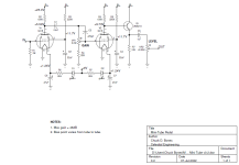
Mini Tube v0.2.png
V2 on the left, V1 on the right.

Mini Tube Pedal v0.2 breadboard 01.jpg
 
Last edited:
No heat issues. I know it's counter-intuitive because we're used to tubes getting hot enough to raise blisters.
The filament voltage & current are 1.25V and 10mA, respectively. R6, R7, D1 & D2 drop the +9V down to 1.25V. When I add the charge pump, I'll still power the filaments the way you see here. The +25V rail is only for the plates & screens. The plate currents are 194μA and 153μA. The screen currents are both 60μA. The total current draw on the +25V rail is less than 0.5mA. This whole thing is very low power.
 
God that was super quick thanks Dave

Why am I surprised?

Excellent I'll definitely give it a go

Just for info Wilhelm at different noises on insta is happy for anyone to build, mod, dissect or improve the freeverb

This is his first real spring tube reverb circuit it does work I've got it on the breadboard at the moment trying to figure it out with my limited knowledge

He wants it to remain free to DIYers hence the name and not be built on a commercial basis

He's got a few designs using various sub miniature tubes on his insta so well worth a follow if you're into messing with these tiny tubes the freeverb schematic is also now posted there
 
Last edited:
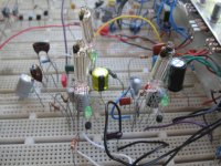
Latest iteration, loosely based on the Fender Deluxe Reverb preamp. No more BJT buffer at the end. D4 increases the headroom on the 3rd stage. The BIAS control is an experiment. Below noon V3 is biased cold, above noon it's biased hot. Varying the bias changes the headroom, compression and harmonic content. Still running the B+ on a bench supply.

Mini Tube v0.3.png

1st stage on the right, 2nd stage on the left, 3rd stage in the background.
Mini Tube Pedal v0.3 breadboard 02.jpg
 
Those tubes don't have much gain. The 1st & 2nd stages each make about 25dB gain. The tone stack eats about 20dB. The last stage makes about 20dB gain. There's about 6dB loss in C10, R11 & R12 at 1KHz. Comes out to around 45dB overall gain, depending on the freq and how the tone controls are set.

BTW, D1-D3 are just there to indicate that filament current is flowing on the breadboard. In a pedal, I'd delete D1-D3 and increase the resistance of R6, R10 & R16.
 
Hey…what’s up? I wired the input & tone stages. I didn’t do a power stage, because I’m lazy and have a 3-channel programmable PSU.
Any side bets that I can or can’t fit it on a 400-hole doodad?

wDEnprm.jpg
 
The filament is rated for 1.25V ±0.25V. Be careful you don't burn it out.
These are directly-heated tubes, which means that the filament IS the cathode. For maximum gain, we want the filament bypassed to ground. One side of the filament connects directly to ground, the other side is bypassed to ground via the 47μF cap.

What's the voltage on the plate (pin 1) and screen (pin 2)?
 
Sorry, I had my DMM grounded to the incorrect rail the 2nd time. It reads 1.59v at the plate, and 24.4v @ the screen. The filament (pin 5) is also 1.59v.

Edit: I should probably lower that eh?
 
I set the filaments as close as I can to 1.25V. The rated filament current is 10mA, so you should be able to calc the dropping resistor req'd.

That screen voltage is way too high, which might explain why the plate voltage is way too low. Check your wiring.

On mine, the screens on the 1st & 2nd stages run close to 12V. The plates are 6.8V and 6.2V, respectively. There is bound to be some variation from one tube to another. My B+ supply is 25V.
 
Yeah, I had some stray connections per SOP. I added the rest of it, and will step through voltages and audio. I have a few spares if they didn’t survive my mishandling.
 
Here's the latest revision. I spent some time (maybe too much time) tweaking this and that in an effort to get the most out of those little tubes. I started out with the purist attitude of no semiconductors in the signal chain. I ended up needing a few diodes and a JFET in the circuit in order to get things just right. I had to reacquaint myself with directly-heated tetrodes. The last time I worked on a circuit with a directly-heated tetrode, it was being used as the electron gun in a free-electron laser. But that's another story...

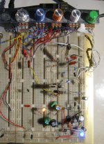
Clear knob - LEVEL
Blue knob - BASS
Orange knob - MID
White knob - TREBLE
Green knob - GAIN

Mini-Marshall v0.33 breadboard 02.jpg

The circuit is loosely based on the first two stages and tone stack in a Marshall amp.

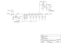
The bias on these tubes is very sensitive to the screen grid voltage, so I ended up putting in a regulator to stabilize the screen voltage. There is a 5V reg for the filament supply with series resistors on the filament leads to control bias and filament current. A charge pump makes the 25V plate supply. The orange & blue LEDs are there to tell me that the filament and plate/screen power are on. The first stage plays clean with single-coil pickups and is on the edge of breakup with Humbuckers. At medium GAIN settings, V2 provides some 2nd & 3rd harmonics. At higher GAIN settings, D1 & D2 kick-in and make some additional distortion, mostly 3rd & 5th harmonic. It's important to not drive the grids too hard, or the sound turns to shit. The LEDs & diodes take care of limiting the grid voltage. Q1 provides buffering to drive the Tone Stack. The maximum clean output is a little over 3Vp-p with BASS, MID & TREBLE at noon. The maximum dirty output is over 7Vp-p. I tried adding another gain stage between V1 & V2, but I didn't like the tone as much as with two stages. I did not try pushing this with another pedal; I ran the guitar straight in.

Mini Marshall v0.33 sheet 1.png


Mini Marshall v0.33 sheet 2.png
 
Last edited:
Back
Top