This Week on the Breadboard: Germanium / FET Overdrive

Chuck D. Bones

Circuit Wizard
I've been fooling around with FET Overdrive circuits that use Germanium diodes for clipping off and on for a few weeks now. I've finally arrived at something that I like. I might try some alternate tone stacks, although this one works pretty well. This started out as a four stage overdrive with three hard clippers, but I felt it was a bit much. Some of you might like it that way. Up front is a Sziklai gain stage. Q1 needs to be low-capacitance so it doesn't muffle the pickups. I used a 2SK193, but a J201 would also work. Fiddle R6 to get about 5V on Q2-E. Q1 & Q2 drive the first hard clipper (D1 & D2). Use whatever germanium diodes you like, low leakage is preferable, but not mandatory. I deliberately keep the impedance in that part of the circuit low to accommodate diode leakage. The ATTITUDE switch kicks the 2nd-stage gain up by 16dB. With the ATTITUDE set for Mellow, D1 & D2 do all of the clipping; Q3 barely tickles LEDs D3 & D4. Set the ATTITUDE to Kerfuffle and the LEDs light up. It pops a bit when you switch the ATTITUDE switch. It's not intended to be an on-demand boost. The LEDs are followed by a Fender-style tone stack. I left one of the caps out because DC blocking is not required in this circuit. The last stage provides gain recovery after the tone stack and a low-impedance output. Q4's gain is set so it will not saturate for any control setting. The FAT switch does the usual thing, it tightens the bass so you can drive this with humbuckers and not get too muddy. Unless you want to. Between the GAIN control and the ATTITUDE switch, you can easily dial-in the desired amount of dirt and then control it from the guitar. It's still a work in progress, but it's close enough to done that I wanted to share it.
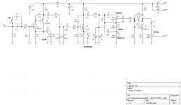
Ge-FET OD v1.1.png
Left to right: Volume, Bass, Mid, Treble, Attitude, Fat, Gain. The Ge diodes are under the switches. The red LEDs are in the middle of the board.
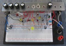
Ge - FET OD v1.1 - 02.jpg

Bonus topic:
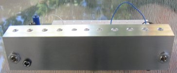
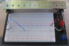
I bought some breadboards on eBay, picked up some scrap aluminum at the local metal yard, did a little cutting and drilling. Voilà! Three more breadboards. The panel has enough holes for eight pots and three toggle switches. The binding posts came with the breadboard and can be used to hook up aux power.
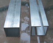
cut aluminum box tubing.jpg

Celestial Breadboard 02.jpg

Celestial Breadboard 04.jpg
 
Last edited:
You really know how to press my curiosity killed the cat buttons left right and center... ;)
Great stuff.
What would happen if we replace R 12 with a 500R pot of 1k pot to make attitude dial able rather than switchable, like a pre gain type of ting? Would it scratch like the proverbial cat when you dial it? Or more like Karen's attitude when she wants to speak to the supervisor?
 
You mean Helen, right?

I tried a few values for R12 and concluded that it didn't merit a pot. The values I liked were 0Ω, 150Ω and 470Ω. I was thinking about how to vary the ATTITUDE without scratching or popping. It's basically done the same way I vary the gain of the 1st stage. Connect a large cap (47μF or more) in series with a C1K pot. Put those in parallel with R12 and make R12 = 1K. Make R9 = 3.3M to get the bias where it belongs. Feel free to try it out and draw your own conclusions. The pot could be replaced with a stomp switch - no popping.
 
Last edited:
I think I'm going to have to quit my job so I can keep up with building all the cool circuits you come up with, Chuck. Love everything about this one.

That breadboard setup is super slick, too. Are the aluminum rails glued to the board? Don't see any screws.
 
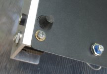
Good questions. The bracket is mounted with two #6 screws, nuts & tooth washers. There is enough of a burr around the holes in the black steel plate to ensure electrical contact between the plate & the aluminum bracket.

Celestial Breadboard 06.jpg

I rounded the corners on the top. The entire bracket, including the outside edges, was buffed with steel wool. Just enough to barely break the edges.

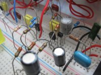
Celestial Breadboard 05.jpg

This was one of my more neat assembly jobs. Note how the pinouts for Q1 & Q2 mesh nicely.

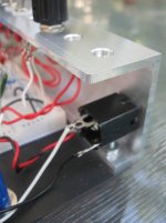
Celestial Breadboard 07.jpg

This bracket was the prototype. I have to pull the jacks to get the pots above them in or out. Not a big deal, but avoidable if I can relocate the jacks.
 
Last edited:
I used a Makita radial arm saw. I normally use it for carpentry, but that blade is a mean muh-fuh and has no problem with aluminum, just gotta take it slow to avoid galling. I clamped a couple blocks of wood onto the platform to make a jig that kept the aluminum aligned and steady. Set the depth limiter on the blade so it would only cut one wall. Made one pass with the blade, flipped the piece over and made the 2nd cut.
 
I've a question regarding the schematic. I started this a few minutes ago and whammo! there's a fat switch at the pulldown. I'm showing 1.192nF[1.004nF-out] & 45.1nF[44.6nF-out] at the junction of C1 / C2 / R2 depending on S2 position. At R2 / R3 I am seeing 1.196nF & 7.31nF / S2 . Is this the expected capacitance at this node? If not, I've fuddled something at the gate (literally of Q1 hah!).
Thanks for

Edit:...oops. My poptart came up, sorry...thanks for reading!
 
Last edited:
Measuring parts in-circuit can be problematic because the other components can mess-up the measurement. I'm not following you 100%. Tell me where you are placing both meter leads and which parts are installed on the breadboard.
 
  • Like
Reactions: fig
Normally I wouldn't measure in-circuit, but as this was a bit different, I was curious what the "net capacitance" would be. The only components in-play are up to and including R3.
One lead is at IN (S2 / C1 / R1), the other at R2 / R3 .

I'm not following you 100%
It's a toaster pastry. Not very good for you though.
 
Here it is on the scope. Channel 1 @ IN, Channel 2 @ R2 / R3. Pics show S2 effect.

1 kHz @ 4 Vpp Sine.

l66MjiI.jpg

7X40yRD.jpg
 
The presence of R2 is screwing up the measurement. Your meter doesn't expect there to be so much resistance and can't account for its effects.

C1, C2, R2 & R3 form a high-pass filter. The high-pass corner freq is either

1 / (2*π*C1*(R2+R3)) = 332Hz

or

1 / (2*π*(C1+C2)*(R2+R3)) = 7Hz

You're driving the circuit at 1KHz, so you won't see much effect from switching S2. Try testing it at 100Hz and you'll see more of a difference.
 
  • Like
Reactions: fig
I've been tweaking the components a bit. I had the wrong cap installed for C7 and that caused me to chase my tail for a while.
R19 is now 1K and R16 is now 3.3M. The last stage was clipping at extreme settings and now it's not.
C8 is now 47nF. The difference is not huge. The midrange notch is moved up in freq and is not quite as deep.
C10 is now 220pF. The tone was too hot with TREBLE dimed. Now I like the entire range.
Added a 220pF cap from Q3-G to Q3-D. This cap only comes into play when ATTITUDE is engaged. It shaves a little off the top end before the LED clippers.
I tried keeping R12 constant and switching in a bypass cap to boost the gain, but it didn't sound as good as shorting out R12. Seems that kicking up the bias increases the aggression when ATTITUDE is engaged and that's key to the tone. If you want ATTITUDE to be continuously variable, then replace R12 with a C1K pot and put a 1K resistor in parallel.

I'm calling it done. Enough turd polishing. :poop:
 
While it's still steaming...
footnote: I realized I have a RC series calculator in the EEToolkit app. Eureka.
Thanks.
 
Back
Top