This Week on the Breadboard - ROG Azabache

Chuck D. Bones

Circuit Wizard
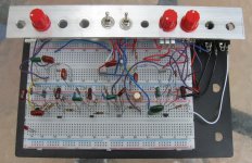
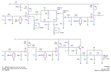
I had been meaning to breadboard this one for some time now, finally got around to it during a break from compressors. I built it by the book, except I used fixed resistors (3.3K, 15K, 15K 15K) instead of trimpots and auditioned JFETs until I hit the recommended drain voltages. I tried a couple of mods: asymmetric clipping on stage 3 and increased gain on stage 2, but neither sounded as good as the original design. I am not a fan of the cab sim at the tail end, makes it sound too thin. This circuit would benefit from a PRESENCE control after Q5. It's a clever design, similar to some of the other ROG amp-in-a-box circuits. The LEDs up front are for protection only and don't normally conduct. The 1st & 2nd stages don't distort, in fact the diodes just after the TONE control don't get enough signal to turn on. Q3, Q4 and their diodes do all of the clipping. Q5 makes a 2nd-order low-pass at 6.7KHz that simulates the bandwidth of an output transformer.
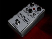
ROG Azabache 01.jpg

ROG azabache.png
 
I had been meaning to breadboard this one for some time now, finally got around to it during a break from compressors. I built it by the book, except I used fixed resistors (3.3K, 15K, 15K 15K) instead of trimpots and auditioned JFETs until I hit the recommended drain voltages. I tried a couple of mods: asymmetric clipping on stage 3 and increased gain on stage 2, but neither sounded as good as the original design. I am not a fan of the cab sim at the tail end, makes it sound too thin. This circuit would benefit from a PRESENCE control after Q5. It's a clever design, similar to some of the other ROG amp-in-a-box circuits. The LEDs up front are for protection only and don't normally conduct. The 1st & 2nd stages don't distort, in fact the diodes just after the TONE control don't get enough signal to turn on. Q3, Q4 and their diodes do all of the clipping. Q5 makes a 2nd-order low-pass at 6.7KHz that simulates the bandwidth of an output transformer.

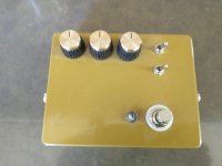
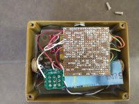
View attachment 24209

View attachment 24203
Opinion. Should I finish your middle finger or build this instead?
 
  • Like
Reactions: spi
I had been meaning to breadboard this one for some time now, finally got around to it during a break from compressors. I built it by the book, except I used fixed resistors (3.3K, 15K, 15K 15K) instead of trimpots and auditioned JFETs until I hit the recommended drain voltages. I tried a couple of mods: asymmetric clipping on stage 3 and increased gain on stage 2, but neither sounded as good as the original design. I am not a fan of the cab sim at the tail end, makes it sound too thin. This circuit would benefit from a PRESENCE control after Q5. It's a clever design, similar to some of the other ROG amp-in-a-box circuits. The LEDs up front are for protection only and don't normally conduct. The 1st & 2nd stages don't distort, in fact the diodes just after the TONE control don't get enough signal to turn on. Q3, Q4 and their diodes do all of the clipping. Q5 makes a 2nd-order low-pass at 6.7KHz that simulates the bandwidth of an output transformer.

View attachment 24209

View attachment 24203
Experimented with a SWTC just before the volume control and it makes wonders to this pedal. It allows me to have the tone control higher (less bass) and cut the excess treble with the SWTC. In this way the overdrive sound is much better (which I disliked before because of either too much bass or ear piercing treble).
 
So basically you're replacing the original one-knob tone stack with a two-knob stack. Lotta ways to do that. Fender/Marshall 2 or 3 knob stack, James, Baxandall, etc.

Can we see a schematic of what you did?
 
So basically you're replacing the original one-knob tone stack with a two-knob stack. Lotta ways to do that. Fender/Marshall 2 or 3 knob stack, James, Baxandall, etc.

Can we see a schematic of what you did?
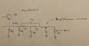
I took your advice for an Presence control and placed it after the Jensen speaker simulation, in the very end just before the volume pot. I took what I had at the moment, a 25k pot in “series” with the circuit (1 & 3 lug) and the wiper attached to a cap tied to ground

It is on the breadboard so I will experiment with it for a while

The problem with the Azabache (for me anyway) is the farty bass distorting with the tone control low, and the excess treble on the other end of the pot. What I was after was the ability to have a thinner sound without the piercing treble. And to have a smoother overdriven sound with the pedal 2F4031B6-6A27-4862-B550-A0549E0A28F0.jpeg
 
Last edited:
I took your advice for an Presence control and placed it after the Jensen speaker simulation, in the very end just before the volume pot. I took what I had at the moment, a 25k pot in “series” with the circuit (1 & 3 lug) and the wiper attached to a cap tied to ground
Another place for a treble cut control is right after Q4. Disconnect the 47K and 100K from the 1nF and 39K and insert a B250K pot between the 100K + 47K and the 1nF + 39K.
 
Another place for a treble cut control is right after Q4. Disconnect the 47K and 100K from the 1nF and 39K and insert a B250K pot between the 100K + 47K and the 1nF + 39K.
I’ll try that too! As a RAT filter control then (variable resistor)?
What is the benefit of placing the presence control there compared to after the speaker simulation?
 
@Chuck D. Bones that “presencepot after Q4” did indeed work out great! I really like the Azabache better with the ability to shave off the treble in the end of the circuit! Even more versatile now. Thanx for your knowledge!
 
Back
Top