Chuck D. Bones
Circuit Wizard
I just had to try this to see what happened. A simple circuit that works quite well!

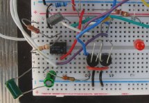
Here's the breadboard. I used a pair of generic Vactrol-type opto-couplers I bought from EG. Makes it easier to test in a lit room compared to an LDR illuminated by two LEDs. LDR (opto) selection is critical. We want an LDR (opto) with a large resistance range and a medium response speed. Too fast and we get distortion at low freq. Too slow and it breathes. Any single FET-input opamp will work. I tried a TL081 and an LF351, both worked well. I originally powered this circuit with ±9V because I already had a charge pump on the breadboard. Then I switched to +9V power, which is how it's configured in the pic below. No difference in performance.

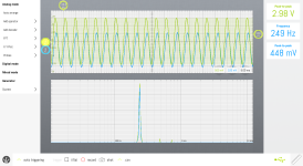
Here's the harmonic spectrum with a large input signal and SUSTAIN dimed. 2nd & 3rd harmonics add up to about 2% THD.

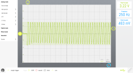
Here's the response to a tone burst. The first cycle is clipped just above the compression threshold by the LEDs. After that, the LDRs take over and keep the signal level just below the clipping threshold.

The next rev has BLEND & TREBLE controls. It's still undergoing testing.

Here's the breadboard. I used a pair of generic Vactrol-type opto-couplers I bought from EG. Makes it easier to test in a lit room compared to an LDR illuminated by two LEDs. LDR (opto) selection is critical. We want an LDR (opto) with a large resistance range and a medium response speed. Too fast and we get distortion at low freq. Too slow and it breathes. Any single FET-input opamp will work. I tried a TL081 and an LF351, both worked well. I originally powered this circuit with ±9V because I already had a charge pump on the breadboard. Then I switched to +9V power, which is how it's configured in the pic below. No difference in performance.

Here's the harmonic spectrum with a large input signal and SUSTAIN dimed. 2nd & 3rd harmonics add up to about 2% THD.

Here's the response to a tone burst. The first cycle is clipped just above the compression threshold by the LEDs. After that, the LDRs take over and keep the signal level just below the clipping threshold.

The next rev has BLEND & TREBLE controls. It's still undergoing testing.


