Chuck D. Bones
Circuit Wizard
[updated]
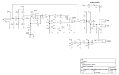
Stephan asked me about some mods to the Roger Mayer Voodoo-1. Here's the schematic I traced from photos of an original pedal. The schematic I found online has many errors, so don't bother looking at that one. Note that this pedal is buffered bypass. Some people will see the LM308 and say "Rat." To that I say "Bollocks." Yes, it has an LM308 and hard clipping, but that's where the similarity ends. Roger Mayer is a clever designer and he did some interesting things here. Q1 is a buffer with 2x gain. It provides a high input impedance, around 400K. Q1 is biased so its collector is at 4.6V. That way, it can be DC coupled to U1 and there's no need for a Vref. Smart. R6 & R7 set the max gain for U1 at 72dB. At higher GAIN settings, the bass is rolled-off by C2. D1-D4 provide hard clipping. They're followed by a modified BMP tone stack. R8 & C6 provide a slight treble cut. R11 limits the amount of treble cut when TONE is at zero. Next comes the LEVEL control and a unity-gain buffer (Q2). The power supply is heavily filtered by C10-C12, R16 & R17. I wondered why Vcc2 is so heavily filtered, then I realized that when U1 is slamming against the rails, power supply noise couples directly to U1's output (pin 6). Vcc3 is further filtered to eliminate power supply noise in the 1st stage. There is less than a 1V drop across R17 because together, Q1 and U1 draw less than 450μA.

So "what's this about mods?" you ask.
Stephan's friend was looking for these three improvements:
1. The ability to dial-down the bass. He runs the GAIN below noon, so C2 is letting all of the bass thru.
2. A mid hump around 750Hz.
3. More volume.
All three are easily accomplished.
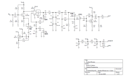
To dial-down the bass, I rearranged the GAIN control and added the BASS control in U1's feedback loop, similar to the Timmy. With BASS at 10, everything gets thru. Turning BASS down to zero attenuates everything below 420Hz.
To get a mid boost, I added a gyrator to the 1st stage: Q2, C2, C3 & R6-R8. I used a MOSFET for Q2 to simplify the biasing. This circuit provides a mid hump that can be varied by VR1. With MID at zero, the 1st stage freq response is flat. With MID at 10, there is a +7dB bump at 750Hz. The freq of the mid hump can be adjusted by changing R6. Since Stephan's friend runs GAIN below noon, I reduced the max gain by making R9 = 1K. People who want more gain can increase VR3 to 500K or even 1M.
Last mod is to increase the volume by adding some gain to the 3rd stage. I tried an LM386 booster in place of the unity-gain buffer, but it had too much gain. A SHO-type booster was just the ticket. Q3 provided a high-impedance load to the LEVEL & TONE pots, a low-impedance output and just the right amount of gain. Max output is over 7Vp-p.
Additional mods:
I broke the connection between D1-D4 so that different diode combinations could be tried. Right now, I'm running germanium for D3 & D4.
I increased C6 to 68pF on my breadboard to reduce the high-order harmonics when U1 saturates.

So how does it sound?
With the GAIN (or guitar volume) set low enough that U1 does not clip, the distortion is smooth and mellow. Drive U1 into saturation and the tone gets hotter and fatter, with more even-order harmonics. With BASS at 10 and MID at zero, it sounds like the Voodoo-1, but has less max gain available.
Personally, I like a slightly darker tone. That can be achieved by increasing C8 to 4.7nF, C10 to 6.8nF and reducing R15 to 3.3K.
Stephan asked me about some mods to the Roger Mayer Voodoo-1. Here's the schematic I traced from photos of an original pedal. The schematic I found online has many errors, so don't bother looking at that one. Note that this pedal is buffered bypass. Some people will see the LM308 and say "Rat." To that I say "Bollocks." Yes, it has an LM308 and hard clipping, but that's where the similarity ends. Roger Mayer is a clever designer and he did some interesting things here. Q1 is a buffer with 2x gain. It provides a high input impedance, around 400K. Q1 is biased so its collector is at 4.6V. That way, it can be DC coupled to U1 and there's no need for a Vref. Smart. R6 & R7 set the max gain for U1 at 72dB. At higher GAIN settings, the bass is rolled-off by C2. D1-D4 provide hard clipping. They're followed by a modified BMP tone stack. R8 & C6 provide a slight treble cut. R11 limits the amount of treble cut when TONE is at zero. Next comes the LEVEL control and a unity-gain buffer (Q2). The power supply is heavily filtered by C10-C12, R16 & R17. I wondered why Vcc2 is so heavily filtered, then I realized that when U1 is slamming against the rails, power supply noise couples directly to U1's output (pin 6). Vcc3 is further filtered to eliminate power supply noise in the 1st stage. There is less than a 1V drop across R17 because together, Q1 and U1 draw less than 450μA.

So "what's this about mods?" you ask.
Stephan's friend was looking for these three improvements:
1. The ability to dial-down the bass. He runs the GAIN below noon, so C2 is letting all of the bass thru.
2. A mid hump around 750Hz.
3. More volume.
All three are easily accomplished.
To dial-down the bass, I rearranged the GAIN control and added the BASS control in U1's feedback loop, similar to the Timmy. With BASS at 10, everything gets thru. Turning BASS down to zero attenuates everything below 420Hz.
To get a mid boost, I added a gyrator to the 1st stage: Q2, C2, C3 & R6-R8. I used a MOSFET for Q2 to simplify the biasing. This circuit provides a mid hump that can be varied by VR1. With MID at zero, the 1st stage freq response is flat. With MID at 10, there is a +7dB bump at 750Hz. The freq of the mid hump can be adjusted by changing R6. Since Stephan's friend runs GAIN below noon, I reduced the max gain by making R9 = 1K. People who want more gain can increase VR3 to 500K or even 1M.
Last mod is to increase the volume by adding some gain to the 3rd stage. I tried an LM386 booster in place of the unity-gain buffer, but it had too much gain. A SHO-type booster was just the ticket. Q3 provided a high-impedance load to the LEVEL & TONE pots, a low-impedance output and just the right amount of gain. Max output is over 7Vp-p.
Additional mods:
I broke the connection between D1-D4 so that different diode combinations could be tried. Right now, I'm running germanium for D3 & D4.
I increased C6 to 68pF on my breadboard to reduce the high-order harmonics when U1 saturates.

So how does it sound?
With the GAIN (or guitar volume) set low enough that U1 does not clip, the distortion is smooth and mellow. Drive U1 into saturation and the tone gets hotter and fatter, with more even-order harmonics. With BASS at 10 and MID at zero, it sounds like the Voodoo-1, but has less max gain available.
Personally, I like a slightly darker tone. That can be achieved by increasing C8 to 4.7nF, C10 to 6.8nF and reducing R15 to 3.3K.
Last edited:


