MichaelW
Well-known member
- Build Rating
- 5.00 star(s)
And design by @HamishR and "Chuckification" by @Chuck D. Bones!
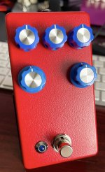
Another great collaborative effort by the super talented folks on this forum. I am SO BLESSED to be a guinea pig for some of these awesome projects!
Details of the evolution of this circuit can be found in Chucks "Timbre Man Breadboard" project thread.
The TL;DR is that it's based on the Danae circuit (Vemuram TSV808) which itself is an interesting mashup of a Jan Ray (Timmy) and TS808.
Very cool pedal but had a lot of kinda useless features and controls.
@HamishR took to modifying it to his liking, and as he and I shared a lot of the same taste in drive pedals, I KNEW I was going to love this. AND I DO!!
It feels to me like a TSV808 with all the useless stuff trimmed away and honing in on what's good about it. @Chuck D. Bones tone stack modifications make all the tone controls much more useful with greater range.
This is a low to medium gain pedal, that kinda shines in the low gain realm but also can sound pretty gnarly with the gain dimed. For the Ge diode I used an ITT Ge diode that measured Vf ~.353 on my CCT. Which translates to mid to upper 200's on a Peak Atlas. The addition of the Ge in the diode mix does a real nice job of fattening up the gain.
The board is @MattG 's layout and he was kind enough to send me one of his boards to try out.
His design has an integrated relay switching and alas, I did not have any "non-latching" relays. All my relays are the latching kind and it didn't make a lot of sense to place an order with Tayda for a single component. (Plus patience is not a virtue I am in possession of an abundance of....hahah)
So Matt gave me instructions to bypass the relay circuitry and wire it up as a standard 3PDT footswtich.
When I was wrapping up the off board wiring this morning and testing the voltages at my bench it worked perfectly! Woohoo!
Super cool overdrive! Thanks all involved!

Trying to keep the wiring for bypassing the relay nice and neat.

The board looks a little sparse with the relay circuitry hahaha. @MattG did a great job keeping the main circuit on the bottom half of the board the relay circuitry to the top half. It was pretty easy peasy to bypass it all and use a standard footswitch.
Also, first time using the new @PedalPCB 3DPT breakout board with the led pads. This is definitely going to make my life easier with builds where I need to put the status LED next to the footswitch.

I recorded a short demo showing the sounds.
Another great collaborative effort by the super talented folks on this forum. I am SO BLESSED to be a guinea pig for some of these awesome projects!
Details of the evolution of this circuit can be found in Chucks "Timbre Man Breadboard" project thread.
The TL;DR is that it's based on the Danae circuit (Vemuram TSV808) which itself is an interesting mashup of a Jan Ray (Timmy) and TS808.
Very cool pedal but had a lot of kinda useless features and controls.
@HamishR took to modifying it to his liking, and as he and I shared a lot of the same taste in drive pedals, I KNEW I was going to love this. AND I DO!!
It feels to me like a TSV808 with all the useless stuff trimmed away and honing in on what's good about it. @Chuck D. Bones tone stack modifications make all the tone controls much more useful with greater range.
This is a low to medium gain pedal, that kinda shines in the low gain realm but also can sound pretty gnarly with the gain dimed. For the Ge diode I used an ITT Ge diode that measured Vf ~.353 on my CCT. Which translates to mid to upper 200's on a Peak Atlas. The addition of the Ge in the diode mix does a real nice job of fattening up the gain.
The board is @MattG 's layout and he was kind enough to send me one of his boards to try out.
His design has an integrated relay switching and alas, I did not have any "non-latching" relays. All my relays are the latching kind and it didn't make a lot of sense to place an order with Tayda for a single component. (Plus patience is not a virtue I am in possession of an abundance of....hahah)
So Matt gave me instructions to bypass the relay circuitry and wire it up as a standard 3PDT footswtich.
When I was wrapping up the off board wiring this morning and testing the voltages at my bench it worked perfectly! Woohoo!
Super cool overdrive! Thanks all involved!

Trying to keep the wiring for bypassing the relay nice and neat.

The board looks a little sparse with the relay circuitry hahaha. @MattG did a great job keeping the main circuit on the bottom half of the board the relay circuitry to the top half. It was pretty easy peasy to bypass it all and use a standard footswitch.
Also, first time using the new @PedalPCB 3DPT breakout board with the led pads. This is definitely going to make my life easier with builds where I need to put the status LED next to the footswitch.

I recorded a short demo showing the sounds.

