Chuck D. Bones
Circuit Wizard
Fender Tone Stacks
One of the first tone stacks designed specifically for guitar was the Fender Treble-Bass tone stack. The one shown below is from the Deluxe Reverb. Regarding Fender's notation here: the TREBLE pot is marked 250KΩ30A. The 30A means that this pot has a 30% audio taper. A 30% audio taper pot reaches a 30% resistance ratio at noon. A linear taper (B-taper) pot reaches a 50% resistance ratio at noon. The A-taper pots we buy from Tayda, Small Bear, etc. are 15% taper pots. In tube amps, this circuit is usually driven by a triode with an output impedance around 30KΩ. This tone stack is usually loaded by a 1M pot. Changing either impedance affects the tuning and signal loss in the tone stack.
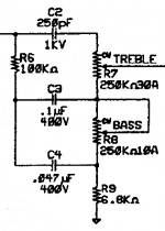
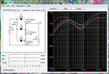
The TREBLE pots controls the balance between high freq stuff that passes thru C2 and the low to mid freq stuff that passes thru R6, C3, C4 & the BASS pot. The BASS pot controls where the low freq cutoff happens. R9 limits the depth of the mid-freq notch. C3's main job is to block DC. It is usually large enough that its exact value does not affect the tone stack's tuning. C2 determines the TREBLE control's high-pass freq. Make C2 larger and more mids get thru when TREBLE is above noon. Make C2 smaller and the mid notch gets deeper and moves up in freq. C4 determines the BASS control's low-pass freq. Make C4 smaller and more mids get thru. The mid notch moves up in freq. R6 is called the "slope" resistor. It affects the balance between the BASS and TREBLE controls, the depth of the mid notch and the overall insertion loss of the tone stack. Making R6 smaller reduces the depth of the mid notch, the strength of the BASS control and the overall signal loss in the tone stack. It should be pretty clear by now that all of these parts interact to some degree. My approach to tuning/modding the Fender tone stack is to start by simulating it with TSC and then doing some breadboard experiments. Because this tone stack typically eats 10 to 20dB of signal, we will probably need a gain recovery stage after it. Here is TSC in action. Note that I made the Mid pot 6.8K and have it dimed. In some circuits, the BASS pot is A1M. There is not much going on between 250K and 1M, so don't expect to get 4x more bass by increasing the BASS pot 4x.
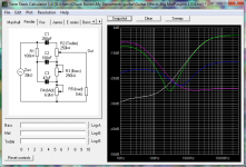
TREBLE = 6, BASS = 2 (blue)
TREBLE = 10, BASS = 0 (white)
TREBLE = 0, BASS = 10 (magenta)
TREBLE = 10, BASS = 10 (green)
If we use this circuit in a pedal, it will be surrounded by opamps or transistors and the impedances are generally much lower than in a tube amp. We can use this to our advantage and scale the impedances of the tone stack to better match the surrounding circuitry. Most pedal builders don't do that and it's a missed opportunity to improve the signal-to-noise ratio. For an extreme example of impedance scaling, check out the Biggus Dickus. The LM386 has a very low output impedance and can source plenty of current, so it makes sense to lower the tone stack's impedance by 25x.
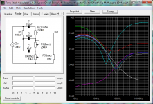
What happens when we add a MID control? R9 in the Deluxe Reverb schematic above is replace with a pot, usually an A10K. Fender used a 30% taper in the Twin Reverb. Note that if all three controls are set to zero, no signal gets thru. The MID control interacts strongly with the BASS and TREBLE controls. If BASS = 10 and TREBLE = 0, MID acts like another TREBLE control. A similar thing happens if BASS = 0 and TREBLE = 10. If BASS & TREBLE are both at 10, the MID controls varies the depth of the mid notch. The MID control cannot make the mid notch go away, we have to turn TREBLE and BASS all the way down to make that happen. Here is a family of curves from TSC. When you click the Sweep button, TSC sets all controls at noon, plots that curve, then runs each control in turn at min and max with the others at noon. What's not presented here is everything at min and everything at max. If you want to see that, give TSC a whirl. The component values shown below are from the Twin Reverb.
Marshall Tone Stack
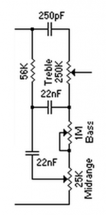
The Marshall Tone Stack, which Fender also uses in some of their amps, connects the MID control in a slightly different way. Instead of connecting the bottom cap (C3 in TSC) to pin 3 of the MID control, it's connected to pin 2. The advantage of this configuration is that even with all three controls at zero, sound still gets thru. This permits different frequency response curves than the Fender tone stack. The price we pay for connecting MID in this fashion is the TREBLE and BASS controls can't make as much boost or cut. Marshall usually drives the tone stack with a cathode follower. Fender does the same thing in a few amps, such as the Bassman 5F6 (the Fender amp that Marshall plagiarized).
Here's the family of curves.
Some pedal circuits use the Fender tone stack but replace some or all of the pots with fixed resistors. The Catalinbread Sabbra Cadabra, ROG Thunderbird and Boss Blues Driver hardwire all three controls to a fixed setting. The Catalinbread Galileo MKII hardwires the BASS & MID controls.
A note on impedance scaling. The idea is to keep the ratios of the R & C impedances the same. If we want to cut the impedance in half, we reduce all of the resistors by 2x and increase all of the capacitors by 2x. No need to hit exact values; the nearest standard value is plenty close.
One of the first tone stacks designed specifically for guitar was the Fender Treble-Bass tone stack. The one shown below is from the Deluxe Reverb. Regarding Fender's notation here: the TREBLE pot is marked 250KΩ30A. The 30A means that this pot has a 30% audio taper. A 30% audio taper pot reaches a 30% resistance ratio at noon. A linear taper (B-taper) pot reaches a 50% resistance ratio at noon. The A-taper pots we buy from Tayda, Small Bear, etc. are 15% taper pots. In tube amps, this circuit is usually driven by a triode with an output impedance around 30KΩ. This tone stack is usually loaded by a 1M pot. Changing either impedance affects the tuning and signal loss in the tone stack.

The TREBLE pots controls the balance between high freq stuff that passes thru C2 and the low to mid freq stuff that passes thru R6, C3, C4 & the BASS pot. The BASS pot controls where the low freq cutoff happens. R9 limits the depth of the mid-freq notch. C3's main job is to block DC. It is usually large enough that its exact value does not affect the tone stack's tuning. C2 determines the TREBLE control's high-pass freq. Make C2 larger and more mids get thru when TREBLE is above noon. Make C2 smaller and the mid notch gets deeper and moves up in freq. C4 determines the BASS control's low-pass freq. Make C4 smaller and more mids get thru. The mid notch moves up in freq. R6 is called the "slope" resistor. It affects the balance between the BASS and TREBLE controls, the depth of the mid notch and the overall insertion loss of the tone stack. Making R6 smaller reduces the depth of the mid notch, the strength of the BASS control and the overall signal loss in the tone stack. It should be pretty clear by now that all of these parts interact to some degree. My approach to tuning/modding the Fender tone stack is to start by simulating it with TSC and then doing some breadboard experiments. Because this tone stack typically eats 10 to 20dB of signal, we will probably need a gain recovery stage after it. Here is TSC in action. Note that I made the Mid pot 6.8K and have it dimed. In some circuits, the BASS pot is A1M. There is not much going on between 250K and 1M, so don't expect to get 4x more bass by increasing the BASS pot 4x.

TREBLE = 6, BASS = 2 (blue)
TREBLE = 10, BASS = 0 (white)
TREBLE = 0, BASS = 10 (magenta)
TREBLE = 10, BASS = 10 (green)
If we use this circuit in a pedal, it will be surrounded by opamps or transistors and the impedances are generally much lower than in a tube amp. We can use this to our advantage and scale the impedances of the tone stack to better match the surrounding circuitry. Most pedal builders don't do that and it's a missed opportunity to improve the signal-to-noise ratio. For an extreme example of impedance scaling, check out the Biggus Dickus. The LM386 has a very low output impedance and can source plenty of current, so it makes sense to lower the tone stack's impedance by 25x.
What happens when we add a MID control? R9 in the Deluxe Reverb schematic above is replace with a pot, usually an A10K. Fender used a 30% taper in the Twin Reverb. Note that if all three controls are set to zero, no signal gets thru. The MID control interacts strongly with the BASS and TREBLE controls. If BASS = 10 and TREBLE = 0, MID acts like another TREBLE control. A similar thing happens if BASS = 0 and TREBLE = 10. If BASS & TREBLE are both at 10, the MID controls varies the depth of the mid notch. The MID control cannot make the mid notch go away, we have to turn TREBLE and BASS all the way down to make that happen. Here is a family of curves from TSC. When you click the Sweep button, TSC sets all controls at noon, plots that curve, then runs each control in turn at min and max with the others at noon. What's not presented here is everything at min and everything at max. If you want to see that, give TSC a whirl. The component values shown below are from the Twin Reverb.

Marshall Tone Stack
The Marshall Tone Stack, which Fender also uses in some of their amps, connects the MID control in a slightly different way. Instead of connecting the bottom cap (C3 in TSC) to pin 3 of the MID control, it's connected to pin 2. The advantage of this configuration is that even with all three controls at zero, sound still gets thru. This permits different frequency response curves than the Fender tone stack. The price we pay for connecting MID in this fashion is the TREBLE and BASS controls can't make as much boost or cut. Marshall usually drives the tone stack with a cathode follower. Fender does the same thing in a few amps, such as the Bassman 5F6 (the Fender amp that Marshall plagiarized).

Here's the family of curves.

Some pedal circuits use the Fender tone stack but replace some or all of the pots with fixed resistors. The Catalinbread Sabbra Cadabra, ROG Thunderbird and Boss Blues Driver hardwire all three controls to a fixed setting. The Catalinbread Galileo MKII hardwires the BASS & MID controls.
A note on impedance scaling. The idea is to keep the ratios of the R & C impedances the same. If we want to cut the impedance in half, we reduce all of the resistors by 2x and increase all of the capacitors by 2x. No need to hit exact values; the nearest standard value is plenty close.


