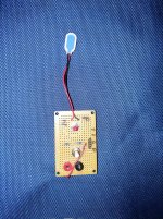
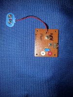
I had my own pcb fabbed for measuring jfets Vp and Idss. I find it extremely convenient compared to setting it up on breadboard, or even a vero build, since I have board mounted DC jack and toggle switch (Vp / Idss switch), and some instructions printed on the board. I the circuit from here (fig 10).
I think an even better pcb version could be made here, including sockets for easily measuring transistor hfe and leakage. PNP and NPN, with just a simple multimeter with micro-amps mode. I've been using the method from smallbear's article.
I think that the documentation would need to be more involved than the typical project here so that people don't have to go hunting for the theory, and the procedure is clearly explained.


