vigilante398
Authorized Vendor
Hi there! I had a couple requests to talk about my design process for tube preamps, so figured I would write up a super boring guide with way too many words and way too many pictures. I’m going to be using a lot of resources from https://www.ampbooks.com/mobile/amplifier-calculators/ which has some amazing online calculators for tubes so we don’t have to do any dreaded math. I'll post links to the calculators I used here at the end.
DISCLAIMER - I do not consider myself an expert on tubes, everything written here is my take based on my experience. I have a degree in electrical engineering, but I got it WAY after tubes were considered "obsolete" so all of my knowledge on the topic comes from hands-on experience and/or from reading books and articles from people that I consider to be experts.
Also - The voltages used in tube amps and even preamp pedals CAN KILL YOU and will hurt the whole time you're dying. I will always tell people if you aren't comfortable taking the necessary safety precautions to deal with high voltage, you shouldn't build or work on high voltage circuits.
So what the hell is a tube?
The most common tubes in guitar audio come in two types, triodes and pentodes (we'll ignore rectifier tubes as they don't handle audio). We’re just going to discuss triodes today, if I get super excited I may write something up about pentodes, but don’t hold your breath.
A triode is called a triode because it has three signal connections: plate (anode), grid, and cathode. The most common tube we see around is the 12AX7, which is a dual triode, it has two triode stages in it. The 12AX7 and other tubes in the 12A*7 family have two additional pins for filaments (heaters) and a filament center tap. I have a separate talk about tube heaters where I can go into depth later, but for now I’m going to start with triode gain stage basics.
So how the hell do I hook up a triode?
For those that have dealt with common-emitter transistor stages, the common-cathode gain stage will look very familiar:
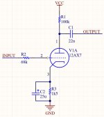
This is a typical “Fender” input stage, but adjusting values can change the tone. So let’s look at how this stage will behave, then we can look at changing it. Using the calculators from the ampbooks website we see that we have a voltage gain of 61.54 (35.78dB), which is LOUD! We also see that we have an output impedance of 38.46k, which isn’t important for most preamp stuff, we can get into that some other time.
Aside from the gain, we can look at the frequency response of the stage using these calculators. The two main components that will affect your response will be the coupling capacitor and the cathode bypass capacitor. What I do generally is look at the cathode bypass cap first. With the Fender values above, this is what we can expect:
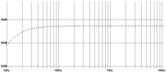
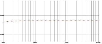
For guitar this is fine, but if you’re a bassist you may be wanting a bit more rumble in the low end. For my bass preamps I typically raise that to 47uF or 100uF. This is what the response looks like with a 100uF cathode bypass capacitor:
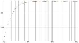
So that will give us an idea of what the stage wants to give us on the output, but what actually passes through is going to be determined by your coupling capacitor. In the case of our Fender circuit, this is what the response looks like with a 22nF coupling capacitor:
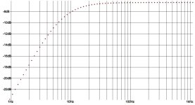
Really not bad at all. Again for bass you still may want to add a little more rumble, so here’s what the response looks like with a 100nF coupling capacitor:
So how about gain?
There are two factors that impact the gain, plate resistor and cathode connection. If there is no cathode bypass cap then the cathode resistor directly impacts gain, but if you have the cap then the cathode resistor doesn’t affect gain much and it’s all on the plate resistor. We saw that with a bypass cap on the cathode and a 100k plate resistor we have a voltage gain of 61.54 (35.78dB). If we keep everything else the same and just raise the plate resistor to 220k, we get a voltage gain of 77.88 (37.83dB), a plate resistor of 470k would give us 88.26 (38.92dB). We need to be careful going too high though, as raising the plate resistor also raises the output impedance of the stage, and if it goes too high we could run into trouble with whatever it connects to down the road. I rarely go higher than 220k, and in high gain preamps it’s common to leave the plate resistors at 100k or 220k and just add more stages to get the additional drive.
SO TELL ME ABOUT OVERDRIVE!!!!!
So that’s where it gets interesting. A single triode stage with a guitar plugged straight into it will not overdrive. It can easily give you enough output to act as a clean boost and push your amp into overdrive, but a single triode stage in isolation won’t distort. For that you need a second stage that will get pushed by the first stage. Generally you want a gain control between your two stages so you can control how hard the first stage pushes the second stage. You’re not actually controlling how much output the first stage has, you’re just dumping part of it to ground with the pot so you only get as much as you want.
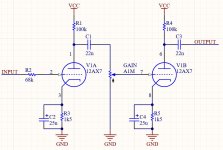
If you were going to stop there it’s also a good idea to throw a “Master Volume” on the very end so you can dial back the output from the second stage and get more of the dirt from the first stage pushing it. Also since we’re at this point, may as well throw a pull-down on the input.
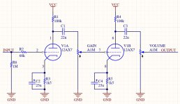
Something to keep in mind when connecting multiple gainstages: when the gain is anywhere below 100%, we have some resistance in-line between the coupling cap of stage 1 and the grid of stage 2. However with the gain cranked we are going straight from coupling cap to grid, and this is generally frowned upon for stability reasons. So it’s common to either have an in-line resistor with the gain pot or a voltage divider which sets a maximum gain level and also ensures you will always have a grid resistor. I personally use voltage dividers before the gain pot, like this:
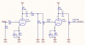
And frankly you could stop right there and call it a day. Swap the capacitor values on that schematic and throw it in a 1590B with a high voltage SMPS and you literally have one of my best-selling preamps, “Space Heater”. But you could also add tone controls, you could add a JFET boost to the beginning, you could add more tubes to the end, it’s up to you. There is quite frankly no limit to how many gain stages you can connect, and the more stages you connect the more cascaded gain you can get, and thus the thicker the distortion.
Anyway, that’s it for now, I hope you’ve gained something out of my ramblings, and stay tuned for more ramblings!
Links to the calculators I used here:
Gain and output impedance: https://www.ampbooks.com/mobile/amplifier-calculators/output-impedance/
Cathode bypass capacitor frequency response: https://www.ampbooks.com/mobile/amplifier-calculators/cathode-capacitor/
Coupling capacitor frequency response: https://www.ampbooks.com/mobile/amplifier-calculators/coupling-capacitor/
DISCLAIMER - I do not consider myself an expert on tubes, everything written here is my take based on my experience. I have a degree in electrical engineering, but I got it WAY after tubes were considered "obsolete" so all of my knowledge on the topic comes from hands-on experience and/or from reading books and articles from people that I consider to be experts.
Also - The voltages used in tube amps and even preamp pedals CAN KILL YOU and will hurt the whole time you're dying. I will always tell people if you aren't comfortable taking the necessary safety precautions to deal with high voltage, you shouldn't build or work on high voltage circuits.
So what the hell is a tube?
The most common tubes in guitar audio come in two types, triodes and pentodes (we'll ignore rectifier tubes as they don't handle audio). We’re just going to discuss triodes today, if I get super excited I may write something up about pentodes, but don’t hold your breath.
A triode is called a triode because it has three signal connections: plate (anode), grid, and cathode. The most common tube we see around is the 12AX7, which is a dual triode, it has two triode stages in it. The 12AX7 and other tubes in the 12A*7 family have two additional pins for filaments (heaters) and a filament center tap. I have a separate talk about tube heaters where I can go into depth later, but for now I’m going to start with triode gain stage basics.
So how the hell do I hook up a triode?
For those that have dealt with common-emitter transistor stages, the common-cathode gain stage will look very familiar:

This is a typical “Fender” input stage, but adjusting values can change the tone. So let’s look at how this stage will behave, then we can look at changing it. Using the calculators from the ampbooks website we see that we have a voltage gain of 61.54 (35.78dB), which is LOUD! We also see that we have an output impedance of 38.46k, which isn’t important for most preamp stuff, we can get into that some other time.
Aside from the gain, we can look at the frequency response of the stage using these calculators. The two main components that will affect your response will be the coupling capacitor and the cathode bypass capacitor. What I do generally is look at the cathode bypass cap first. With the Fender values above, this is what we can expect:

For guitar this is fine, but if you’re a bassist you may be wanting a bit more rumble in the low end. For my bass preamps I typically raise that to 47uF or 100uF. This is what the response looks like with a 100uF cathode bypass capacitor:

So that will give us an idea of what the stage wants to give us on the output, but what actually passes through is going to be determined by your coupling capacitor. In the case of our Fender circuit, this is what the response looks like with a 22nF coupling capacitor:

Really not bad at all. Again for bass you still may want to add a little more rumble, so here’s what the response looks like with a 100nF coupling capacitor:

So how about gain?
There are two factors that impact the gain, plate resistor and cathode connection. If there is no cathode bypass cap then the cathode resistor directly impacts gain, but if you have the cap then the cathode resistor doesn’t affect gain much and it’s all on the plate resistor. We saw that with a bypass cap on the cathode and a 100k plate resistor we have a voltage gain of 61.54 (35.78dB). If we keep everything else the same and just raise the plate resistor to 220k, we get a voltage gain of 77.88 (37.83dB), a plate resistor of 470k would give us 88.26 (38.92dB). We need to be careful going too high though, as raising the plate resistor also raises the output impedance of the stage, and if it goes too high we could run into trouble with whatever it connects to down the road. I rarely go higher than 220k, and in high gain preamps it’s common to leave the plate resistors at 100k or 220k and just add more stages to get the additional drive.
SO TELL ME ABOUT OVERDRIVE!!!!!
So that’s where it gets interesting. A single triode stage with a guitar plugged straight into it will not overdrive. It can easily give you enough output to act as a clean boost and push your amp into overdrive, but a single triode stage in isolation won’t distort. For that you need a second stage that will get pushed by the first stage. Generally you want a gain control between your two stages so you can control how hard the first stage pushes the second stage. You’re not actually controlling how much output the first stage has, you’re just dumping part of it to ground with the pot so you only get as much as you want.

If you were going to stop there it’s also a good idea to throw a “Master Volume” on the very end so you can dial back the output from the second stage and get more of the dirt from the first stage pushing it. Also since we’re at this point, may as well throw a pull-down on the input.

Something to keep in mind when connecting multiple gainstages: when the gain is anywhere below 100%, we have some resistance in-line between the coupling cap of stage 1 and the grid of stage 2. However with the gain cranked we are going straight from coupling cap to grid, and this is generally frowned upon for stability reasons. So it’s common to either have an in-line resistor with the gain pot or a voltage divider which sets a maximum gain level and also ensures you will always have a grid resistor. I personally use voltage dividers before the gain pot, like this:

And frankly you could stop right there and call it a day. Swap the capacitor values on that schematic and throw it in a 1590B with a high voltage SMPS and you literally have one of my best-selling preamps, “Space Heater”. But you could also add tone controls, you could add a JFET boost to the beginning, you could add more tubes to the end, it’s up to you. There is quite frankly no limit to how many gain stages you can connect, and the more stages you connect the more cascaded gain you can get, and thus the thicker the distortion.
Anyway, that’s it for now, I hope you’ve gained something out of my ramblings, and stay tuned for more ramblings!
Links to the calculators I used here:
Gain and output impedance: https://www.ampbooks.com/mobile/amplifier-calculators/output-impedance/
Cathode bypass capacitor frequency response: https://www.ampbooks.com/mobile/amplifier-calculators/cathode-capacitor/
Coupling capacitor frequency response: https://www.ampbooks.com/mobile/amplifier-calculators/coupling-capacitor/
Last edited:

