Fingolfen
Well-known member
If you remember back a few weeks ago, I posted my first "semi-original" hybrid pedal - the Dimetrodon Distortion. The original versions consisted of two boards, a hand etched Distortion+ or Drivestortion board with a hand etched BMP Tone Stack (the DD1A) or an Effects Layout commercial Drivestortion board with a hand etched BMP Tone Stack (the DD1B). On further reflection, I thought it would be cool if I could combine the boards into a single etch and not have to use hookup wire to connect the two together. So, I decided to try and merge my graphics skills with what I've learned about electronics and circuit design over the past year or so!
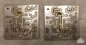
Originally PCBs were hand drawn and etched, which is why PCBs from the 1960s and 1970s look so different from the ones today. They weren't constrained by CAD programs, though they couldn't take advantage of their functionality either. That being said, both the Drivestortion and BMP tone stack circuit diagrams were fairly simple. As I'd paid to license both from Effects Layouts, I went ahead and tried my hand at combining the two. Fortunately the 9V power rails were in compatible positions, so I was able to run power from one board to another. With the circuit powered, it was just a matter of connecting the output of the Drivestortion board to the input of the BMP Tone Stack. I wanted to try and keep the board as compact as possible, and I didn't want traces essentially running around the perimeter of the board. I therefore took the Drivestortion output and re-routed it up toward the tone stack rather than taking it around the whole outside of the board. This meant I had to use one jumper (you can see it in the image below), but it did nicely mate the two boards together. I also moved the output of the tone stack to the right-hand edge of the PCB (viewed from the component side).
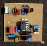
For my first build with the new board, I decided to take a bit of a risk and build a combination I hadn't prototyped yet. Both of my previous builds had been what would now be called a "B3" (see the table below) which combines the MXR Distortion+ from 1980 with a '75 Ram's Head Tone Stack. For this build I decided to go with an A2 - the 1977 Grey 250 combined with a '73 Ram's Head Tone Stack.

First and foremost - and slightly to my shock and amazement - the pedal fired up and worked perfectly right off the bat. The volume, distortion, and tone controls all worked perfectly. The A2 configuration does sound a bit more "old school" than the B3 configurations I'd built previously, but it is still absolutely killer!
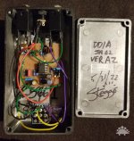
As this is the prototype, the wiring is still a little bit of a dog's breakfast as I'm running the LED wire and 4.7K resistor off board. Honestly, I was just hoping it would work! Future versions will be a bit neater, but as you can see it fits quite nicely in the enclosure. There is room for a battery, and I think I'll try and incorporate one in future versions of the pedal.
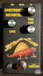
I had intended to go with a 2 and 1 configuration of knobs, but the BMP Tone Stack is so narrow, I had to shift the gain knob down in the enclosure (even though the pins from the potentiometer are in line with the Level knob on the PCB). Honestly, I think I really like the asymmetrical look of the final enclosure. As to the artwork, for that I have my lovely wife to thank! If you look really hard at the real thing, you'd be able to see her signature at the tip of the tail. This prototype still needs its "Steggo" badge on the front, but I'll be adding that soon!

Originally PCBs were hand drawn and etched, which is why PCBs from the 1960s and 1970s look so different from the ones today. They weren't constrained by CAD programs, though they couldn't take advantage of their functionality either. That being said, both the Drivestortion and BMP tone stack circuit diagrams were fairly simple. As I'd paid to license both from Effects Layouts, I went ahead and tried my hand at combining the two. Fortunately the 9V power rails were in compatible positions, so I was able to run power from one board to another. With the circuit powered, it was just a matter of connecting the output of the Drivestortion board to the input of the BMP Tone Stack. I wanted to try and keep the board as compact as possible, and I didn't want traces essentially running around the perimeter of the board. I therefore took the Drivestortion output and re-routed it up toward the tone stack rather than taking it around the whole outside of the board. This meant I had to use one jumper (you can see it in the image below), but it did nicely mate the two boards together. I also moved the output of the tone stack to the right-hand edge of the PCB (viewed from the component side).

For my first build with the new board, I decided to take a bit of a risk and build a combination I hadn't prototyped yet. Both of my previous builds had been what would now be called a "B3" (see the table below) which combines the MXR Distortion+ from 1980 with a '75 Ram's Head Tone Stack. For this build I decided to go with an A2 - the 1977 Grey 250 combined with a '73 Ram's Head Tone Stack.

First and foremost - and slightly to my shock and amazement - the pedal fired up and worked perfectly right off the bat. The volume, distortion, and tone controls all worked perfectly. The A2 configuration does sound a bit more "old school" than the B3 configurations I'd built previously, but it is still absolutely killer!

As this is the prototype, the wiring is still a little bit of a dog's breakfast as I'm running the LED wire and 4.7K resistor off board. Honestly, I was just hoping it would work! Future versions will be a bit neater, but as you can see it fits quite nicely in the enclosure. There is room for a battery, and I think I'll try and incorporate one in future versions of the pedal.

I had intended to go with a 2 and 1 configuration of knobs, but the BMP Tone Stack is so narrow, I had to shift the gain knob down in the enclosure (even though the pins from the potentiometer are in line with the Level knob on the PCB). Honestly, I think I really like the asymmetrical look of the final enclosure. As to the artwork, for that I have my lovely wife to thank! If you look really hard at the real thing, you'd be able to see her signature at the tip of the tail. This prototype still needs its "Steggo" badge on the front, but I'll be adding that soon!


