Using dpdt in place of 3pdt

Connjams

New member
Hi I'm looking to use multiple pcbs in one enclosure and only want 1 of the three controlled by a stomp with the other 2 using toggle switches.

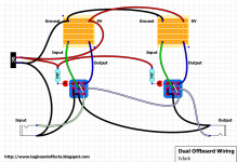
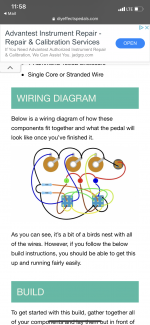
Do I just leave the anode/ cathode and sw holes open on the pcb? And then wire up the dpdts like the photo attached? Are there any mods needed to doing a swap like this bc I know the resistor for the LEDs are usually built into the pcb so do I need to remove that as well??

Any guidance in doing some would be super appreciated! Also if anyone wants to share some multi pcb builds that'd also be awesome so I can have some inspiration/ frame of reference for my build!

cheers!
 

Attachments

  • BCD6B4DA-47AE-406C-9EFA-D7D529127C2E.gif
    BCD6B4DA-47AE-406C-9EFA-D7D529127C2E.gif
    86.8 KB · Views: 7
  • 0C0CB601-9D2D-48A5-A6C5-A6194A78774F.png
    0C0CB601-9D2D-48A5-A6C5-A6194A78774F.png
    64 KB · Views: 8
There's combo wiring info here


If you're not having LED indication you can leave that and the CLR off the pcb no need to jumper those on pedalpcb true bypass boards

You'll see the LED and CLR connection in the power section normally bottom left of the schematic obviously make sure it is the CLR resistor you're leaving out by continuity checking it with the SW or LED cathode K pad it's usually a 4K7

I'm assuming you're using one 3PDT switch with LED and DPDT toggles for the rest with no on/off LED indication

So you'd just do this below adding DPDTs as required jumpering in and outs across

This is 3 circuits using one 3PDT with LED and 2 DPDTs without as long as your in and out jacks are grounded it'll be fine if you don't want any LED indication you could use a DPDT stomp switch + your DPDT toggle switches

20210306_090433.jpg
 
Thank you so much for the response!! Just a quick follow up I saw a "better" true bypass method and will probably follow that schematic since the pedal pcbs have the grounding connection.

my idea is a little wonky:

ABY splitter->
A channel: dpdt->dpdt-> out 1
B channel: 3pdt-> out 2

the ABY has a lot going on but does this wiring work out? I haven't done anything with multiple pedals so I'm just trying to gather all the info possible before trial and error time lol
 

Attachments

  • 4F4A429B-0EB3-40AE-93C7-3834DB37E5D5.jpeg
    4F4A429B-0EB3-40AE-93C7-3834DB37E5D5.jpeg
    381.1 KB · Views: 20
  • FE9692FD-FA3D-4713-B092-A004689AEC26.png
    FE9692FD-FA3D-4713-B092-A004689AEC26.png
    696.2 KB · Views: 11
  • 3CB6CCE9-C947-41D8-AB23-D880D5C51B41.png
    3CB6CCE9-C947-41D8-AB23-D880D5C51B41.png
    1,017.1 KB · Views: 10
Back
Top