
Just put together and it’s not my first pedal but my first op amp drive or buffered pedal. The only few deviances are carbon film resistors here or there and approx 150pf subbed for 100pf ceramics because that’s all I had. I did screw up and printed the template not quite full size so I couldn’t squeeze the panel mount jacks and instead used some old school trs switchcraft jacks I had hanging around. I just tied grounds on those because I won’t need switching for batteries. I had a pack of 10 L7812a transistors so I swapped out 1 with no change….I’m stumped please help!?
You are using an out of date browser. It may not display this or other websites correctly.
You should upgrade or use an alternative browser.
You should upgrade or use an alternative browser.
SOLVED Valhalla distortion triumphant!
- Thread starter dbfmixn
- Start date
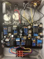
Show us Pictures of PCB & Footswitch & Jack wiring!Just put together and it’s not my first pedal but my first op amp drive or buffered pedal. The only few deviances are carbon film resistors here or there and approx 150pf subbed for 100pf ceramics because that’s all I had. I did screw up and printed the template not quite full size so I couldn’t squeeze the panel mount jacks and instead used some old school trs switchcraft jacks I had hanging around. I just tied grounds on those because I won’t need switching for batteries. I had a pack of 10 L7812a transistors so I swapped out 1 with no change….I’m stumped please help!?
Can you check that your Guitar In & Amp Out cable Jack tip & ring have Continuity with the PCB In and Out pads & Ground pads.Just put together and it’s not my first pedal but my first op amp drive or buffered pedal. The only few deviances are carbon film resistors here or there and approx 150pf subbed for 100pf ceramics because that’s all I had. I did screw up and printed the template not quite full size so I couldn’t squeeze the panel mount jacks and instead used some old school trs switchcraft jacks I had hanging around. I just tied grounds on those because I won’t need switching for batteries. I had a pack of 10 L7812a transistors so I swapped out 1 with no change….I’m stumped please help!?
Those TRS jacks can cause problems!!!
So I replaced the trs jacks with mono. I have continuity from guitar to PCB trace. I did have a problem replacing the voltage regulator as the ground lead would not come out of trace hole. So that extra ground wire is improv. I get negative 9v at power input and to positive side of first diode and that’s it. No sound in bypass as I believe this isn’t wired for true bypass
Attachments
Test matching circles for Continuity:So I replaced the trs jacks with mono. I have continuity from guitar to PCB trace. I did have a problem replacing the voltage regulator as the ground lead would not come out of trace hole. So that extra ground wire is improv. I get negative 9v at power input and to positive side of first diode and that’s it. No sound in bypass as I believe this isn’t wired for true bypass

You are going to have to remove the PCB board & show GOOD picture of solder side!Yes all spots corresponding to the picture or testing fine

Lmao seared caps is what’s for dinner!I think Mr PCB is right! Sometimes it's the simplest things...
I also find that box caps work best before being mauled by a shark.
I have never used that type so I was wondering about the negative 9v he mentioned.I may be looking at this wrong, but it looks like your DC jack is wired backwards to me.
Live & Learn dbfmixn.

Glad you got it working! Sometimes the solution is so simple it often gets overlooked. What did you use for the bottom tread part?Put some lipstick on this pig
Yea but it’s smooth not fizzy like some. Reminds me of Mesa rectifier sound. Great tone shaping with different eq options. Quiet in between the notes as if were gatedI kind of think of Diezel as a metal head kind of melt your face off high gain distortion. Is that what this pedal is
Preverb
Active member
That description actually sounds pretty good. I have so many drive pedals I want to build now...Yea but it’s smooth not fizzy like some. Reminds me of Mesa rectifier sound. Great tone shaping with different eq options. Quiet in between the notes as if were gated