Waddle Box Problems

Alexander Maier

New member
Hello,

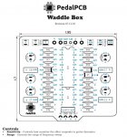
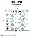
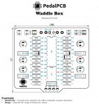
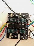
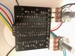
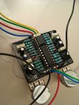
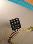
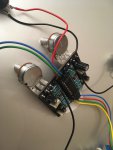
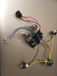
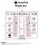
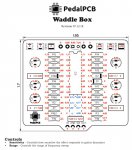
today I received my kit for the Waddle Box (DOD FX25 Clone). The documentation was very good and I build the parts together. When I tested the Waddle Box I can only hear a constant noise. I have looked at all and I think everything is build together as it should be. All parts are on the right place. The D1, D2, D100 was inserted as the ring on the diode goes to the quatratic hole.

What can be the problem?

Thanks

Alexander
 
really hard to say with that little information. could be lots of things. you need to provide more info and pictures of both sides of the board.
1. does the bypass work OK? 2, is power connected properly? 3. are any ICs oriented correctly? 4. same for transistors 5. is the noise in the circuit only there when a guitar is plugged in? 6. Does the noise change when you turn the pots on your effect? What about when you turn the knobs on your guitar? what are the voltage readings on the ICs or transistors in the circuit? those are the same questions you need to go through yourself as well to try to figure out what might be wrong with a pcb project --- sometimes you will figure the problem out and get it working right away, other times you will use that info to share with others on a forum and get suggestions on what to check next.
 
Thanks for the information. I have made some pictures.

1.) The Bypass works
2.) The Power Connection is ok. LED is running and I measured 9V on the platine.
3.) The IC's - I think - are orientad correctly
4.) The transistors are oriented correctly
5.) The diodes are oriented correctly - I think
6.) The noise is only on the output signal when the pedal is activated (no noise at bypass). There is no change when the pots (on the pedal or guitar) are turned.

I have made a test: On the input signal I have running some MP3 player (to get continuous input) and I get a full output when bypassed. When the pedal it active I get a noise (ground smoking - I do not know the right translation) an a very low signal of the MP3 input.

I think I will solder the connections of the pots better. Where do I have to measure the voltage on the IC's.

Alexander
 

Attachments

  • IMG_1727.jpeg
    IMG_1727.jpeg
    481 KB · Views: 25
  • IMG_1728.jpeg
    IMG_1728.jpeg
    515.4 KB · Views: 25
  • IMG_1725.jpeg
    IMG_1725.jpeg
    624 KB · Views: 24
  • IMG_1726.jpeg
    IMG_1726.jpeg
    477.3 KB · Views: 19
  • IMG_1730.jpg
    IMG_1730.jpg
    536.9 KB · Views: 19
  • IMG_1729.jpg
    IMG_1729.jpg
    499.8 KB · Views: 20
Your overall construction looks good. I don't see any likely shorts on the board. You can check the circuit diagram in the build docs to see where the power is supposed to go in the board. most folks will turn then knobs on a project fully in one direction and take the voltage measurements at every pin on an IC and write them down. then turn the knobs in the other direction and write down the voltages again. you do that because some projects are changing the voltage on a chip when you rotate the dials. I don't know if the pots on your project would affect the voltage on the pins. for that matter, I'm not quite sure what the Waddle Box is supposed to do. Usually with a sensitivity adjustment it would either be a "wah" type of filter effect, or maybe a noise gate. either way you should be getting some signal going through it, an no noise drowning it out.

are you also sure that you are putting your sound into the "IN" jack and have the output going to the "OUT" jack? the bypassed signal still works either way, but not the effect. sometimes it is easy to get the plugs reversed when you are testing them out of the box.

I would also use your soldering iron and retouch all of the connections on your resistors and your capacitors to make sure they have shiny solder on them and are connected to the PCB.
 
I am sure to used the correct jacks - I also tried it in the "wrong" way. Bypass is perfect. I have retouched all connection with my soldering iron. The "noise" is now not hearable, only a little rustle (what can be from the preamp of my poweramp). I also measured all connections with the ports in the middle and noted them on the picture. Then I have looked on the diagram an looked for the connections between the parts. There I have checked the measured voltage. All seams ok.

But I have learned that a resistor reduces the voltage. But I have a lot of resistors (R8, R7, R6, R13, ...) where the voltage on both pins seams to be the same. I myself ask me: What would be the correct voltage values to be expected?

I hope the screenshots are ok.
 

Attachments

  • Bildschirmfoto 2019-03-01 um 12.30.00.jpg
    Bildschirmfoto 2019-03-01 um 12.30.00.jpg
    218.1 KB · Views: 21
  • Bildschirmfoto 2019-03-01 um 12.34.01.jpg
    Bildschirmfoto 2019-03-01 um 12.34.01.jpg
    158.5 KB · Views: 23
That is very thorough voltage measurements, excellent!

Something is definitely odd about the voltages around IC1... Can you pull out the IC and measure the voltages on each pin of the IC socket again?
 
Thanks! I have now measured with the IC1 pulled out at the pins from IC1. The IC1 is MC1458P (this should be the same als LM1458). The IC2 is LM13700N. I have got the kit from a German distributor. Could this be the problem?
 

Attachments

  • Bildschirmfoto 2019-03-01 um 13.59.17.jpg
    Bildschirmfoto 2019-03-01 um 13.59.17.jpg
    126.9 KB · Views: 14
Do you have another dual opamp you could pop in there and try? TL072, JRC4558, etc?

It certainly appears like that opamp is defective.
 
I bought a new opamp MC1458P and replaced the one inserted. Still no effect, but if I increase the gain on my amp I get a pulsating noise when the effect is on. Bypass works. So I measured once time.
 

Attachments

  • Bildschirmfoto 2019-03-02 um 11.46.17.jpg
    Bildschirmfoto 2019-03-02 um 11.46.17.jpg
    117 KB · Views: 9
Hmmm, so the voltages have changed considerably, and are closer to what would be expected, but still not quite right...

Just for the heck of it, can you pull out IC2 (leave IC1 installed) and remeasure the voltages around IC1?
 
You should have something in the neighborhood of 4.5V on pins 1, 2, 3 and 5, 6, 7. Your voltages on pin 4 and 8 are normal.
Ok, I have looked at the diagram and measured the following:

Input 9V Power --> D100 --> 8,72V --> R101 (22k) --> 4,02V (VREF) --> R2 (470K) --> 0,54V --> PIN3 on IC1

After this three resistors there is not something in the neighborhood of 4.5V. Seams that the resistor values are not correct? Make it sense to check the others?
 
R2 should "pull up" pin 3 of IC1 to near Vref (4.5V). Pin 3 is high impedance so there should be very little voltage dropped across R2. Pin 1 and 2 should follow.

I just noticed something about your voltage measurements in the most recent picture. You have 4.49V on the left side of R3, but 0.47v / 0.55V on Pin 5 of IC1. Something isn't right there. Those two points are directly connected and should read the same voltage. If those measurements are correct there must be a damaged trace there.
 
Thanks, I have carefully measured once more with no signal on the input and all IC's inserted. On pin 1,2 and 3 of IC1 I have only about 3,65-3,95V. On pin 5 there are 3,19V als about on pin of R3.

R100 is about 0V - My LED has stopped working :( But I think this is not actually a problem.

What I see is that there is about 8,2V on pin 7 of IC1 (also on the connected pins of R4 and C4)

---

I have now spend lot of time about measuring and there seams not be a end. The waddle box is closed to the basket bin :(
 

Attachments

  • Bildschirmfoto 2019-03-06 um 09.07.09.jpg
    Bildschirmfoto 2019-03-06 um 09.07.09.jpg
    116.7 KB · Views: 13
Back
Top