What else is on the breadboard? - The Mona Lisa Simpson OD

Chuck D. Bones

Circuit Wizard
This started out as an investigation into the Apocalypse Audio Mona Lisa Overdrive, but quickly took on a life of its own. The Mona Lisa uses four transistors: a JFET source-follower input, a 2-stage Si transistor amplifier and another JFET source-follower for the output. I hate to waste JFETs, so I replaced the source-follower input with a Darlington emitter follower (Q1). The 3rd stage has a very low output impedance and doesn't need an output buffer, so the source-follower output got tossed overboard. I bumped the max gain up by 6dB and added a TONE control. Works well with Si transistors and gets just a little sweeter with Ge for Q3. The DC feedback loop around Q2 & Q3 keeps Q3's bias stable. This circuit is very flexible when it comes to transistors, just about anything will work. I did not need to adjust any resistors when changing Q3 from Si to Ge.
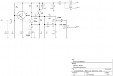
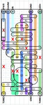
Mona Lisa Simpson v1.0 sch.png
This thing really surprised me with how good it sounds. It has a tight bottom end, maybe a little too tight. I'm still fiddling with C5. Max gain is a modest 57dB. With single coil pickups, it plays clean when GAIN is at noon. Humbuckers require setting GAIN down around 10:00 for clean playing. Clipping comes on very smoothly as GAIN is advanced. Chords are clear, even with GAIN dimed. There is a nice midrange honk at the higher GAIN settings. I'm definitely going to build this one as an actual pedal, not just a toy on a breadboard.
 
Wow, that looks pretty sweet.
Any issues using a JFET for Q1 as long as you use a 2M2 for R1? I has many of those and no darlingtons.
 
JFET will work fine, but you will have to dial-in the bias by adjusting R1 or R4 because all stages are DC coupled. You want about 3.8V on Q3-C for maximum headroom. MPSA13's are $0.10 at Tayda, you might want to pick some up on your next order.
 
Hey man, why is there sometimes a cap and a resistor in parallel in a signal path. Is that some kind of filtering arrangement? I see there's one there on the 9v line too.
 
Cool!
Does anyone know if this would be comparable in sound to the Way Huge Pork Loin (PedalPCB Lamb Chop), which is supposedly based on a Neve console? I love that pedal. But it has a lot of knobs and a lot of parts.
 
In your schematic yeah, but occasionally I see a resistor and cap in parallel in the signal path, say between op amp stages too.
It depends on the specific circuit. In the MLS, R9 provides negative feedback on Q3 for the purpose of stabilizing the bias. That same negative feedback also reduces the gain and we don't want that, so we bypass R9 with C6 so that there is negative feedback at DC, but not for AC signals. It's a gradual transition from DC, where the frequency is zero and C6 acts like it isn't there, to guitar frequencies where C6's impedance is comparable to R9's impedance. So in that sense, it does act like a high-pass filter with a corner freq around 50Hz.
 
Last edited:
Chuck, when you say you hate to waste JFETs, could you explain what you mean by that?

I think it's my Scottish heritage talking. JFETs are more expensive and harder to come by than BJTs, so I only use JFETs where they are essential to achieving the tone I'm after. Any of us would be hard-pressed to hear the difference between a source follower and an emitter follower in a guitar pedal, so I went with an emitter follower.

JFETs have a very high input impedance, but so do Darlington BJTs. There's the convenience of not having to select a transistor for Vp. BJTs are very repeatable (silicon ones anyway); JFETs not so much.

what would a scotsman do.jpg
 
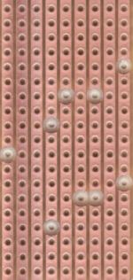
you-sure-got-some-purty-holes.jpg
 
I can see why you added the image of the underside of your vero board. As someone who takes great pride in the drillage of cuts in vero board I applaud your skill. Simply beautiful cuts. I have to agree with jubal81. Hauntingly perfect.
 
Another Deliverance reference.

But seriously folks, a drill press with an accurate stop and a sharp drill bit is all it takes. Once I had the stop set, I drilled 9 holes in about 15 sec. I used to cut Vero holes by hand with a pin vise. Then I was lucky to cut one hole per minute.

Thanks, Hamish, I wasn't trying to show off. I posted that pic in case anyone wanted to know where to make the cuts.
 
Well I was being facetious and admiring at the same time. I didn't think you were trying to show off. Actually I thought it was a good idea to show what the board looks like at various stages. It's something we should probably do more of for those who are new to this.
 
Back
Top