BuddytheReow
Breadboard Baker
This is the Test Kitchen, so let's talk about switches! In the pedal building world we really only come across 4 different kinds of switches: toggle, rotary, push button (stomp usually), and DIP. The different kinds of switches merely indicate how you 'activate' the switch. I'll explain the types once we cover how a switch works in general.
So what exactly is a switch? A more technical answer is that a switch is an electromechanical device that (dis)connect a path in an electrical circuit and/or divert the electrical current from one connection to another.
When we talk about switches and describe them (their name mostly) we talk about poles and throws. A "pole" indicates the number of circuits/connections that switch can control and a "throw" tells us the number of contact points.
The simplest switch possible is a single pole, single throw switch. In a schematic it would look like the top diagram. This one connection is either open or closed. It is how you control the light on your workstation lamp regardless of how you turn it on (push a button or turning a knob)

You can see it is one pole because only one circuit (wire) is involved on the left (schematics tend to flow left to right). It is one throw because the switch can only control the contact point going to the output.
Here's what one looks like. It is a toggle switch and we've all seen them.

The next step up is known as a single pole, double throw switch (SPDT). In a schematic it would look like the bottom diagram.

It is one pole because because there is only one circuit involved at the 'input'. 2 throws because the switch can control the electrical flow to 2 separate contact points here. An example of this in our world may be to select the value of the output capacitor (100n vs 1n) like this.

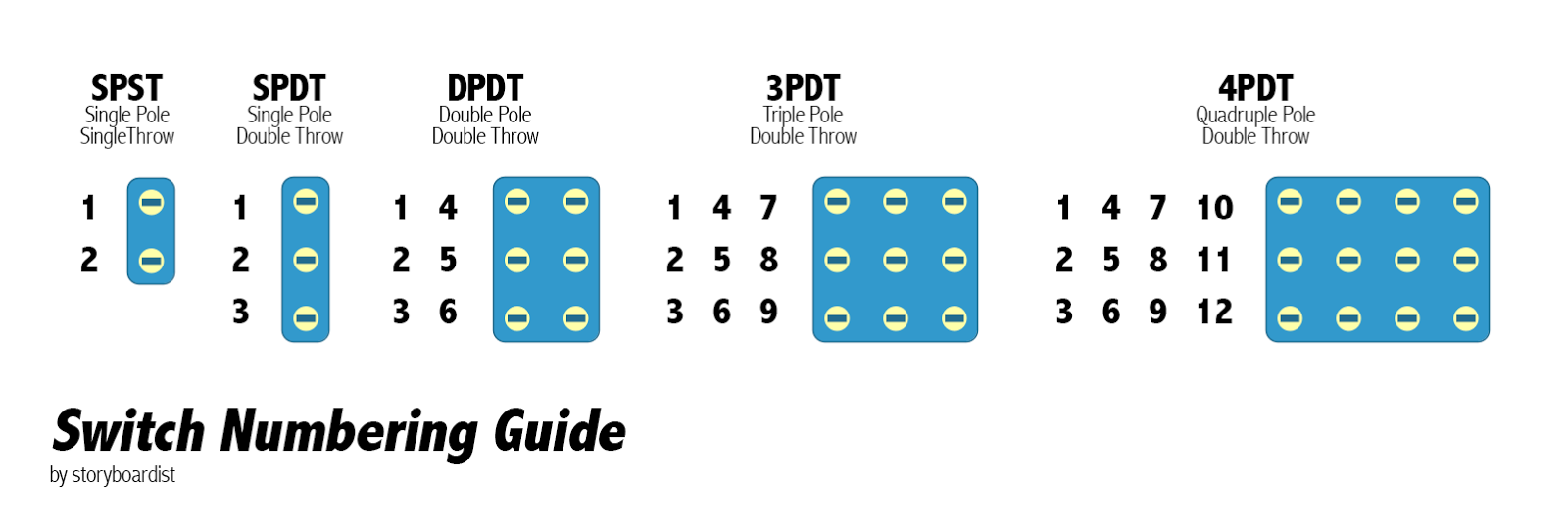
Now that you've got the basics down let's talk about double poles. 2-pole switches have 2 separate inputs controlled at the same time. Here's a really good visualization to explain the difference when you have one or two throws. I'll let this do the talking instead of me writing it up here. If you've got questions here either write them below or message me.

Let's take the next step up. The one you all use in your pedal builds: the 3PDT stomp switch!

Using the same methodology as above, 3 poles (inputs) are controlled at the same time and is in the middle horizontal row based on the pictures above and below.

Let's walkthrough what happens on your builds when you use your stomp switch. Keep in mind this is the classic way to do true bypass here. The orange wire on the left goes to your guitar input jack and the orange wire on the right goes to your output jack to your amp.

Looing at the 'lug map' above, let's figure out together what 'position 1' does. When position 1 is activated we have 3 separate connections: 2-3, 5-6, and 8-9. 2 and 8 we have already determined that those are our input/output jacks. 5 is ground. We also see that there is a jumper wire between 3 and 9. Put these two together and we determine that the guitar signal goes into lug 2, out lug 3, into lug 9, and out lug 8. It completely 'bypasses' the circuit since no connections are being made to the PCB. Position 1 must be true bypass! What about pins 5 and 6? What are they doing here? Good question! Since 5 and 6 are connected here we can figure out that 6 goes to ground. There is a jumper that goes from 6 to 1 and 1 is the input to your PCB. We can now determine that the input to your PCB goes to ground and blocks off any noise the circuit may make.
Position 2 obviously means we activate the PCB effect, but let's walkthrough it anyways. 3 connections are made here: 1-2, 4-5, and 7-8. 1-2 means that our guitar signal is coming from the input jack into the PCB input. 7-8 is the output from the PCB to the output jack (your amp). 4-5 connects ground to the PCB, including the LED. You now have a fully connected connected pedal. We're only talking about switches here, so the DC power jack is separate.
Hopefully you've got a good understanding now of how a switch operates in terms of poles and throws. It can get more complicated in terms of the number of poles and throws, but the concept is still the same.
Now let's talk about the different types of switches.
Toggle Switches
A toggle switch in our world most commonly looks like the first picture above of a red switch (I'm running out of pics to put in here, AHHH!!). Flip the arm one way or the other to activate.
ON/ON
I will use this example of the pins here. It is a SPDT and if your switch is a DPDT also consider pins 4-6. Remember, the "pole" according to my methodology is the middle pin here (2 and 5)
1 - 2 - 3
(4)-(5)-(6)
In an on/on switch there are only 2 positions: a connection between 1-2 OR a connection between 2-3. A connection either way will always be made.
For the record you can turn ANY double throw into a single throw switch: simply omit a connection to pin 3 (and 6 if a double pole) and it's now an on-off switch. Buy extra double throws or look for a prettier looking SPST switch.
ON/OFF/ON (SPDT or DPDT for us)
In a toggle switch, there are actually three positions here that can be used, left-middle-right or up-center-down depending on how you're looking at it. Using the same example here:
1 - 2 - 3
The "on" portions we have already talked about. The middle position is what stands out and simply means that NO connection is made to either pin 1 or 3 in my example. How can this be useful? Let's say on a breadboard you have 2 sets of hard clipping diodes going to ground: D1/D2 and D3/D4. Using the far left position of the switch allows you to activate D1/D2 and the far right activates D3/D4. The middle position here actually cuts off the diodes entirely for a different sound in your circuit.
ON/ON/ON (DPDT mostly for us)
This one can get confusing. This configuration gets separated into 2 types: Type 1 and Type 2 (duh!). This was already discussed in a separate thread here but I will mention it for completeness. There are three positions: up, middle, and down. Up and down have already been covered, but the middle position is what makes this stand apart. The best way to show type 1 and type 2 is to look at the picture below. Make sure you check which type of switch you need while sourcing your parts!

Rotary Switches
Here's a Tayda link: https://www.taydaelectronics.com/rotary-switch-1-pole-12-position-alpha-sr2611f.html
The oversimplification of a rotary switch is that it is activated when you twist the knob. Many table/desk lamps use a rotary switch but that is a single pole mostly. When you turn the knob it 'clicks' and the number of poles/throws determine how many 'clicks' the switch will have. This can get complicated quickly to determine which 'click' of the knob controls what. Use a DMM on the continuity setting to figure that out rather than me explaining that process here.
Push Button (Stomp) Switches
This is your 3pdt stomp switch used to turn your pedal on or off. I don't think I need to mention much else other than they make others that are controlled with your finger instead of your foot.
DIP Switches
Here's a tayda link: https://www.taydaelectronics.com/dip-switch-6-positions-gold-plated-contacts-top-actuated.html
These kinds of switches go directly on your PCB, are pretty small, contain multiple switches, and cannot be controlled externally once you box up your build. Think of it as an IC chip but it's only a bunch of switches on it or as a trimmer: it's kind of a 'set it and forget it' mentality here, but obviously you can go in and tweak it to your tastes depending on how these behave in the circuit.
Momentary vs Latching
Latching switches are more common for us. It simply means that when you activate a switch it stays that way until you physically activate it again. When you flip a toggle switch or step on your stomp switch you hear an actual 'click'.
Momentary switches make the (dis)connections when you push the button or toggle switch. There are springs in there to bring it back to the normal position. Think of this as a kill switch on your guitar. Buckethead has one and uses it a lot.
Is one better than the other here? There are tradeoffs and it all depends why you are using a momentary or latching switch. The best example in the pedal building world of a momentary switch is for relay bypassing. What is it and why should you care? Well, relay bypassing is a different way to hook up your 3pdt switch to achieve true bypass. Coda Effects does an excellent job of explaining it here if you're interested. This short answer is that relay bypass system with a momentary switch lasts a lot longer (allegedly) than a 3pdt latching switch, but it takes more components to make it work. PedalPCB has a few relay boards in the utility section if you want to look more into this.
So, that's it! I think I've covered just about everything I can think of when it comes to switches and guitar or bass pedals. Any comments or questions please leave below.
BuddyTheReow
So what exactly is a switch? A more technical answer is that a switch is an electromechanical device that (dis)connect a path in an electrical circuit and/or divert the electrical current from one connection to another.
When we talk about switches and describe them (their name mostly) we talk about poles and throws. A "pole" indicates the number of circuits/connections that switch can control and a "throw" tells us the number of contact points.
The simplest switch possible is a single pole, single throw switch. In a schematic it would look like the top diagram. This one connection is either open or closed. It is how you control the light on your workstation lamp regardless of how you turn it on (push a button or turning a knob)
You can see it is one pole because only one circuit (wire) is involved on the left (schematics tend to flow left to right). It is one throw because the switch can only control the contact point going to the output.
Here's what one looks like. It is a toggle switch and we've all seen them.
The next step up is known as a single pole, double throw switch (SPDT). In a schematic it would look like the bottom diagram.
It is one pole because because there is only one circuit involved at the 'input'. 2 throws because the switch can control the electrical flow to 2 separate contact points here. An example of this in our world may be to select the value of the output capacitor (100n vs 1n) like this.
Now that you've got the basics down let's talk about double poles. 2-pole switches have 2 separate inputs controlled at the same time. Here's a really good visualization to explain the difference when you have one or two throws. I'll let this do the talking instead of me writing it up here. If you've got questions here either write them below or message me.
Let's take the next step up. The one you all use in your pedal builds: the 3PDT stomp switch!
Using the same methodology as above, 3 poles (inputs) are controlled at the same time and is in the middle horizontal row based on the pictures above and below.
Let's walkthrough what happens on your builds when you use your stomp switch. Keep in mind this is the classic way to do true bypass here. The orange wire on the left goes to your guitar input jack and the orange wire on the right goes to your output jack to your amp.
Looing at the 'lug map' above, let's figure out together what 'position 1' does. When position 1 is activated we have 3 separate connections: 2-3, 5-6, and 8-9. 2 and 8 we have already determined that those are our input/output jacks. 5 is ground. We also see that there is a jumper wire between 3 and 9. Put these two together and we determine that the guitar signal goes into lug 2, out lug 3, into lug 9, and out lug 8. It completely 'bypasses' the circuit since no connections are being made to the PCB. Position 1 must be true bypass! What about pins 5 and 6? What are they doing here? Good question! Since 5 and 6 are connected here we can figure out that 6 goes to ground. There is a jumper that goes from 6 to 1 and 1 is the input to your PCB. We can now determine that the input to your PCB goes to ground and blocks off any noise the circuit may make.
Position 2 obviously means we activate the PCB effect, but let's walkthrough it anyways. 3 connections are made here: 1-2, 4-5, and 7-8. 1-2 means that our guitar signal is coming from the input jack into the PCB input. 7-8 is the output from the PCB to the output jack (your amp). 4-5 connects ground to the PCB, including the LED. You now have a fully connected connected pedal. We're only talking about switches here, so the DC power jack is separate.
Hopefully you've got a good understanding now of how a switch operates in terms of poles and throws. It can get more complicated in terms of the number of poles and throws, but the concept is still the same.
Now let's talk about the different types of switches.
Toggle Switches
A toggle switch in our world most commonly looks like the first picture above of a red switch (I'm running out of pics to put in here, AHHH!!). Flip the arm one way or the other to activate.
ON/ON
I will use this example of the pins here. It is a SPDT and if your switch is a DPDT also consider pins 4-6. Remember, the "pole" according to my methodology is the middle pin here (2 and 5)
1 - 2 - 3
(4)-(5)-(6)
In an on/on switch there are only 2 positions: a connection between 1-2 OR a connection between 2-3. A connection either way will always be made.
For the record you can turn ANY double throw into a single throw switch: simply omit a connection to pin 3 (and 6 if a double pole) and it's now an on-off switch. Buy extra double throws or look for a prettier looking SPST switch.
ON/OFF/ON (SPDT or DPDT for us)
In a toggle switch, there are actually three positions here that can be used, left-middle-right or up-center-down depending on how you're looking at it. Using the same example here:
1 - 2 - 3
The "on" portions we have already talked about. The middle position is what stands out and simply means that NO connection is made to either pin 1 or 3 in my example. How can this be useful? Let's say on a breadboard you have 2 sets of hard clipping diodes going to ground: D1/D2 and D3/D4. Using the far left position of the switch allows you to activate D1/D2 and the far right activates D3/D4. The middle position here actually cuts off the diodes entirely for a different sound in your circuit.
ON/ON/ON (DPDT mostly for us)
This one can get confusing. This configuration gets separated into 2 types: Type 1 and Type 2 (duh!). This was already discussed in a separate thread here but I will mention it for completeness. There are three positions: up, middle, and down. Up and down have already been covered, but the middle position is what makes this stand apart. The best way to show type 1 and type 2 is to look at the picture below. Make sure you check which type of switch you need while sourcing your parts!
Rotary Switches
Here's a Tayda link: https://www.taydaelectronics.com/rotary-switch-1-pole-12-position-alpha-sr2611f.html
The oversimplification of a rotary switch is that it is activated when you twist the knob. Many table/desk lamps use a rotary switch but that is a single pole mostly. When you turn the knob it 'clicks' and the number of poles/throws determine how many 'clicks' the switch will have. This can get complicated quickly to determine which 'click' of the knob controls what. Use a DMM on the continuity setting to figure that out rather than me explaining that process here.
Push Button (Stomp) Switches
This is your 3pdt stomp switch used to turn your pedal on or off. I don't think I need to mention much else other than they make others that are controlled with your finger instead of your foot.
DIP Switches
Here's a tayda link: https://www.taydaelectronics.com/dip-switch-6-positions-gold-plated-contacts-top-actuated.html
These kinds of switches go directly on your PCB, are pretty small, contain multiple switches, and cannot be controlled externally once you box up your build. Think of it as an IC chip but it's only a bunch of switches on it or as a trimmer: it's kind of a 'set it and forget it' mentality here, but obviously you can go in and tweak it to your tastes depending on how these behave in the circuit.
Momentary vs Latching
Latching switches are more common for us. It simply means that when you activate a switch it stays that way until you physically activate it again. When you flip a toggle switch or step on your stomp switch you hear an actual 'click'.
Momentary switches make the (dis)connections when you push the button or toggle switch. There are springs in there to bring it back to the normal position. Think of this as a kill switch on your guitar. Buckethead has one and uses it a lot.
Is one better than the other here? There are tradeoffs and it all depends why you are using a momentary or latching switch. The best example in the pedal building world of a momentary switch is for relay bypassing. What is it and why should you care? Well, relay bypassing is a different way to hook up your 3pdt switch to achieve true bypass. Coda Effects does an excellent job of explaining it here if you're interested. This short answer is that relay bypass system with a momentary switch lasts a lot longer (allegedly) than a 3pdt latching switch, but it takes more components to make it work. PedalPCB has a few relay boards in the utility section if you want to look more into this.
So, that's it! I think I've covered just about everything I can think of when it comes to switches and guitar or bass pedals. Any comments or questions please leave below.
BuddyTheReow