
You are using an out of date browser. It may not display this or other websites correctly.
You should upgrade or use an alternative browser.
You should upgrade or use an alternative browser.
Yellow led duo phase
- Thread starter yoole bee
- Start date
Cybercow
Well-known member
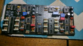
There are already places for two LEDs (one for each LFO) on the PCB. Here's a gutshot of how I did mine. (Note the red circled areas . . . .)

From the front, they are beneath the waterslide decal. The holes were drilled thru the enclosure before applying the waterslide. If you look closely, you can see the slight dimples where the LEDS are. I used 3mm blue LEDs. I repositioned them y using th full length of the legs and used two 90 degree bends. The red insulators are just clipped plastic coffee stirrers.

From the front, they are beneath the waterslide decal. The holes were drilled thru the enclosure before applying the waterslide. If you look closely, you can see the slight dimples where the LEDS are. I used 3mm blue LEDs. I repositioned them y using th full length of the legs and used two 90 degree bends. The red insulators are just clipped plastic coffee stirrers.

K Pedals
Well-known member
You’re gonna have to keep those where they are for the ldr’s...Thank you for your answers but I was talking about the leds circled in green.
The other two LEDs are just on/off.
View attachment 9847
The duo phase relies on adjusting the brightness of those LEDs to change the resistance in the LDRs. Adding another LED in parallel with each one could change those adjustments, perhaps enough to mess up the LFO cycle. But it could be that all you would need to do would be to adjust the brightness levels again after they were hooked up. You could try hooking up an LED with wires attached to the solder side of one of the LEDs and see if it worked before you drill more holes in your enclosure. Having those extra LEDs on wire will also give you more placement options on the enclosure (assuming it works). Give it a try and keep us posted on how it goes.
Cybercow
Well-known member
Doh! You're right. After looking at the schematic, theoretically, additional LEDs could be added to the LFO_A and LFO_B points in the circled part of the diagram. I'd add a CLR to each one, then run the LEDs to ground. They should independently reflect the LFO rate of LFO_A and LFO_B.Thank you for your answers but I was talking about the leds circled in green.
The other two LEDs are just on/off.
Connecting the rate indicator LEDs there should not interfere with the current demands of the LDR LEDs, as they have a separate drive circuit.
So CLR to the LFO_A & LFO_B points, then LEDs to ground. Look at the PCB and schematic to decide where, specifically to connect them to the LFO points.

HiThe duo phase relies on adjusting the brightness of those LEDs to change the resistance in the LDRs. Adding another LED in parallel with each one could change those adjustments, perhaps enough to mess up the LFO cycle. But it could be that all you would need to do would be to adjust the brightness levels again after they were hooked up. You could try hooking up an LED with wires attached to the solder side of one of the LEDs and see if it worked before you drill more holes in your enclosure. Having those extra LEDs on wire will also give you more placement options on the enclosure (assuming it works). Give it a try and keep us posted on how it goes.
I tried by inserting a led in parallel on the led of the lfo and the brightness is disturbed even when adjusting the trimpot...
I'm finishing mine up and figured out a way to make the effect LEDs pulse with the corresponding LFOs. How I did it was take out the 4k7 LED resistors and sub them with a 30k but keep the end closest to the depth pot lifted and solder it to the #3 pin of the depth pot. See pic. Rate LED is soldered in same place on board. I've done this with many other phaser and flanger boards and it works great. I do use high brightness, super low current LEDs though... I figure 30k won't load down an op amp too much.
Attachments
Cybercow
Well-known member
OK, that looks like a working solution. Snicker-snack! Thanks!I'm finishing mine up and figured out a way to make the effect LEDs pulse with the corresponding LFOs. How I did it was take out the 4k7 LED resistors and sub them with a 30k but keep the end closest to the depth pot lifted and solder it to the #3 pin of the depth pot. See pic. Rate LED is soldered in same place on board. I've done this with many other phaser and flanger boards and it works great. I do use high brightness, super low current LEDs though... I figure 30k won't load down an op amp too much.
joaocosta88
New member
This might be a dumb question, but how much current would be considered low current for the LEDs?I'm finishing mine up and figured out a way to make the effect LEDs pulse with the corresponding LFOs. How I did it was take out the 4k7 LED resistors and sub them with a 30k but keep the end closest to the depth pot lifted and solder it to the #3 pin of the depth pot. See pic. Rate LED is soldered in same place on board. I've done this with many other phaser and flanger boards and it works great. I do use high brightness, super low current LEDs though... I figure 30k won't load down an op amp too much.
Also, can the 30k resistor be replaced by a 47k resistor? Or by 16k?
Thanks for the help! I'm building this pedal and this is one of the mods I'm going to attempt
") (and a series/parallel circuit using the splitter-blender by ROG)
(and a series/parallel circuit using the splitter-blender by ROG)Alan W
Well-known member
Using this idea, if one wanted the pulsing external LEDs to be switched (so only on when pedal is in circuit), would the reduced load (when they are off and pedal is bypassed) have any effects on the LFO etc circuitry? I’m sure the low current LEDs would help in this regard.I'm finishing mine up and figured out a way to make the effect LEDs pulse with the corresponding LFOs. How I did it was take out the 4k7 LED resistors and sub them with a 30k but keep the end closest to the depth pot lifted and solder it to the #3 pin of the depth pot. See pic. Rate LED is soldered in same place on board. I've done this with many other phaser and flanger boards and it works great. I do use high brightness, super low current LEDs though... I figure 30k won't load down an op amp too much.
Cybercow
Well-known member
Doubtful that switching the flashing indicator LEDs will have any impact on the current load - as this pedal is NOT battery friendly. Still, low current LEDs for a visual timing cue would be helpful to lessen the load on the LFO opamps.Using this idea, if one wanted the pulsing external LEDs to be switched (so only on when pedal is in circuit), would the reduced load (when they are off and pedal is bypassed) have any effects on the LFO etc circuitry? I’m sure the low current LEDs would help in this regard.
Feral Feline
Well-known member
Just found @Cybercow's Coffee-stirrers idea. Fantastic!
That tip needs to go in the thread about looking at the world through pedal-builder's eyes, but I can't remember the thread title and can't find it again.
I did find the thread with the pizza-box tables that I couldn't find before when I wanted it for the thread I was in that I can't find now...
Reduce, re-use, recycle, adapt...
Using the 30k resistor, the LED is consuming 0.2ma or around 200 microamps, which is basically, nothing. Using a 47k resistor will consume even less current, using 16k, the LED will consume around 0.4maThis might be a dumb question, but how much current would be considered low current for the LEDs?
Also, can the 30k resistor be replaced by a 47k resistor? Or by 16k?
Thanks for the help! I'm building this pedal and this is one of the mods I'm going to attempt
In olden days, 2ma or less would be considered low current for an LED. I don't know what is considered "low current " now.
BTW, the LEDs I used on mine were the 3mm clear green LEDs from tayda electronics.
BrainDrain
Member
When doing this mod is it possible to use a 3k-4k resistor to get the brightness I want or does the resistor have to be a higher value around 16k or more?Using the 30k resistor, the LED is consuming 0.2ma or around 200 microamps, which is basically, nothing. Using a 47k resistor will consume even less current, using 16k, the LED will consume around 0.4ma
In olden days, 2ma or less would be considered low current for an LED. I don't know what is considered "low current " now.
BTW, the LEDs I used on mine were the 3mm clear green LEDs from tayda electronics.
Similar threads
- Replies
- 3
- Views
- 346