SOLVED Lectric FX Karaoke Chorus ticking in bypass

andare

Well-known member
Finished this build and it's perfect but I noticed a faint ticking in bypass when in Chorus mode. I made sure none of the wires are close to any of the ICs. I don't have good shielded wire. The one I have has thin wire surrounded by thick, stiff insulation and it breaks at the solder joints every single time.
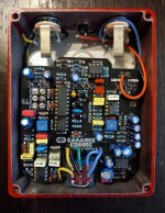
20230716_170424-01.jpeg

I noticed the build docs and the builds I found here don't ground the board input on bypass by I decided to do it to avoid pops. I don't think this has an effect on the output?

Things I tried:
  1. tucking wires as far as possible from any ICs didn't help
  2. grounding board output in bypass with an alligator clip created oscillation
Any ideas?

I would also like to disable the always-on vibrato rate LED which drives me insane. How can I do that safely?

Thanks
 
!. Is C8 Tantalum going in the right direction?
2. Shorten the power wire!
3. Reverse the led to the inside on the PCB.
4. Remove the Input to ground jumper on the Footswitch.
Here is MichaelW Build:
 
!. Is C8 Tantalum going in the right direction?
2. Shorten the power wire!
3. Reverse the led to the inside on the PCB.
4. Remove the Input to ground jumper on the Footswitch.
Here is MichaelW Build:
Thanks for chiming in! I will absolutely try everything you said, I'll just ask a couple of things:
  1. Yes, I just triple checked it against the PCB and the build docs.
  2. Is this going to lessen background hiss or the ticking or both?
  3. I'd like to leave the LED where it is so the hole doesn't show. What happens if I just clip one of the legs? Or maybe I can bridge the two pads? See where it is in the schematic
  4. Is this also a source of noise? Every pedal has this jumper. Is this circuit different?
I'm familiar with Michael's build and used it as inspiration, I left some wires a bit longer because I wanted to route them under the board and not over like in the build docs.

Thanks
As far as the led goes you could just attach it in series with your clr to the dc source to the longer leg (I think anode, I can never remember) and attach the shorter leg to your 3pdt spot where you attach the led from board. Remove the led from the board.
 
As far as the led goes you could just attach it in series with your clr to the dc source to the longer leg (I think anode, I can never remember) and attach the shorter leg to your 3pdt spot where you attach the led from board. Remove the led from the board.
Every time I desolder a component I ruin the board so that's not an option right now.

The LED is connected to the collector of a 2n5088 and to the CLR. What if I clip one of the legs?
 
1. Cut one leg on the existing led & put a led on the pads inside the pedal.
2. The Ground jumper you put on the Footswitch maybe causing the Tick in Bypass.
3. If you still have a Tick after removing jumper, try shortening the power lead.
 
Last edited:
Jumper cut, it still ticks.
I moved the output wire closer to the LM358 and the ticking intensified so it's either shielding the wire or building a shield around that IC. Grounded of course
 
You don't need to shorten it, just move the 9V wire away fro the output jack and see if that helps. You might also try running it with a battery, see if that helps. I have a barrel plug connected to a 9V snap for these occasions. I have had a lot instances where a particular wall wort didn't pair well with a circuit but a different one was fine.

Also, I can't see if the enclosure is painted around the jacks? If so you could check for continuity between the jack and the enclosure, if none, you can sand around the hole so it makes good contact.
This is what I was referring to about Shortening the Power wire & referenced MichaelW Build.
I would also rotate the Output Jack 180 degrees so the Output lead is shorter and connected on the right side of the jack.
 
I moved the 9V wire away in the corner but no difference.
I wrapped solder wick around the output cable and grounded it, no change.
I'll try rotating the jack.
 
I rotated the jack so the output wire is as far as possible from the LM358. Nothing
Finally I made a shield for the LFO with a pot condom and copper wire, grounded to the input jack. Foam on the enclosure lid to keep it pushed against the board. The ticking is practically gone now.
Not an elegant solution.

Thanks everybody for humoring me.
Weird. But glad it’s better now.
 
Back
Top