Should I avoid making input and output signals 'cross' each other?

mzy12

Active member
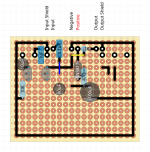
I'm designing my first perfboard layout for an adaptation of a silicon buzzaround from mac over at diystompboxes. I have a feeling the answer i yes, but I'm wonder if I should avoid putting bringing the output signal across the input of the board in order to avoid stuff like cross-talk and oscillation? I have attached a very early draft of my layout done in DIYLC below.


The input crosses the output at the blue jumper wire.

Thanks in advance for any help!
 
It probably doesn't make a practical difference in low to medium gain circuits. If you're going to cross them, do it at a right angle.

Now, high gain circuits are a different story. For those ones, you really want to keep the input well away from the output, and maybe even use shielded wiring at least for the input path (the sensitive one). I've even had to shield the input jack on occasion.
 
Thanks for the response! I suspected as much tbh, I more didn't want to come up with a solution than anything else. It should be easy to fix, I'll just add another row of perfboard above the ground line and bring the signal from there to the output, so it doesn't cross the input anymore. I eventually want to make a PCB out of this, how do you avoid crossing input and output signals on a board where you need to bring the output or the input from one side of the board to the other? In this case, would it be enough to have the signals running on different sides of the board with a ground plane in between them?
 
Since you're prototyping it before making a proper PCB, I wouldn't sweat it too much. If the prototype doesn't squeal, then just make a similar PCB layout. If it squeals, experiment with the proto layout until it stops, then make a similar PCB layout. Theory is only worth a damn if practical experiments agree with it.

And yes, adding some ground-tied copper between in and out traces (in addition to distance) would really help and is good practice.
 
Back
Top