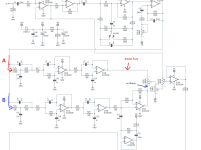
How to add some diode clipping option on Darkglass Alpha Omega circuit (Bass dual distortion) ?

eh là bas ma

Well-known member
I just finished building Aion's Empyrean deluxe project yesterday.


Surprised to see there aren't any diodes except a single 1n5817 for the power section.

I really like both distortions, but i'd like to try to add some toggleswitch somewhere with diodes, just out of curiosity, see how it sounds with led clipping, etc.

From what i can understand with the schematics, it looks like the gain stages for both distortions are built with five RC4559P ICs and one TL72,
but i struggle to get what are the two signal paths, and where i could connect a toggleswitch with diodes.

I suspect some extra diode clipping would be more interesting on the "raw" distortion, to make it a bit smoother.
It will be probably less useful on the first distortion, described as "punchy and tight".

Looking at the schematics, can you tell what are the two signal paths, and where would be the best location for some extra diodes ?

If i had to guess, i'd say the first distortion is made by the TL72, after R5. That would explain why it has more precision, it kind of sounds like a TL72 in its works.
Second distortion is made by five RC4559 cascading gain stages, 2 of them are also used with the last RC4559 to build the EQ at the end of the circuit.
The first RC4559 located at the beginning of the signal path is used to shape the signal before going into the gain stages, like an input buffer ?

...or maybe the first 4559 and the TL72 are just used for Hi-mid and Low switches, and boost the signal before the gain stages.
1st distortion starts at R15 and C9, 2nd starts at R21 and C15 ?

So a good spot to connect a couple of diodes would be between R29 and the Mod control (allowing to dial the balance between both distortions), before the Blend control ?
That way the diodes wouldn't impact the other distortion ?

Every observations and suggestions are welcome !
 
Last edited:
Salut Eh La Bas Ma,

Did you ever figure this out, and how are you liking the circuit?

I am very interested in building this circuit for myself and a friend, because I really do like the [edit: duh. darkglass obsidius] a whole lot.

So, from my li'l rookie eye, it looks like we have a unified signal path with some basic amplification (pin 6 of IC1B is the source of the amplified clean signal for the blend later) and toggles that affect pre-clipping low and mids until we hit the IC2A, which looks like it is governing the amount of clipping gain ("drive") since there's a potentiometer going into pin two with that label.

So far, there's only one signal path. It's at the output on pin1 of IC2A that the signal splits and then is summed with the "Mod" potentiometer after IC5A/ IC3B, so it stands to reason that the clipping is happening in the RC4559s along those two paths, following either a path leading through IC3A/B, or a path leading through IC4A/B and IC5A/B. I couldn't say which is the raw and which the punchy (audio probe!). As you pointed out, it's r15/c9, r21/c15

Where exactly to put the diodes I wouldn't be the person to ask. I see a bunch of feedback loops into the ICs, so I'm pretty sure that's the source of the clipping. What is happening with IC5 I don't know--it could be a recuperation gain?

What you could do is build a two or three-diode PTP ladder and interpose the end of the legs temporarily and manually before the IC array, after the IC array, or in one of the IC feedback loops. You might have to lift a pot or component leg, but it's better than breadboarding the whole thing to me. The only thing you'd really have to watch would be the IC legs. If you bend them more than twice, they are likely to come off.
 
Last edited:
Some thoughts...

IC3a IC3b look to be buffers surrounded by tone shaping stuff... lotta buffering going on in this thing, elsewhere, too...

Not sure if you guys want to add clipping after the tone shaping ie @ IC8a (IC8b is a buffer), 'cause immediately after that is the output (which may work well to add a boost, especially if you add clipping-to-ground somewhere).

The only places I see gain being actively added (and not involved with the BMT-EQ) are:
IC2b and IC2a​
IC5a and IC5b​
IC7a and IC7b​


It would be these places I would look to add soft-clipping, because then you can also swap out a feedback resistor for evening out the gain when adding the clipping-diodes, or even add a pot to tailor the gain to taste on the fly — and so both the gain and clipping could be on a footswitch for an extra "channel".


My initial instinct is to add the clipping diodes to IC2 (breadboarded for either op-amp to see which sounds/works better — 'a' or 'b').

I look forward to seeing what you come up with and what works.
 
Did you ever figure this out, and how are you liking the circuit?
I was busy with harvesting grapes lately. I built the circuit just before leaving and i just got back (2025 is going to be a good year for french wine, at least in Anjou).

So far i didn't try to add diodes in the circuit, yet.

Both distortions sound great as it is, the mod control allows to dial some interesting sounds, similar to what we can do when we run 2 distortions in parallel with a mixer and a blend control.

The 1rst distortion is close to a B3k, except it's not a C-MOS IC design, so the gain texture is slightly different. It's a refined sound, like a river going through a city with its banks made of bricks, peaceful and civilized.
2nd distortion gives a more open sound, as if there is less tone shaping and we can hear the gain texture from the ICs more clearly. This one sounds more like a wild mountain river or a water fall.


Not sure if you guys want to add clipping after the tone shaping
I dont think the 1rst distortion needs diode clipping. In my opinion it would be interesting to add diodes only on the 2nd distortion path.
So that we can mix the 1rst distortion with a more compressed 2nd distortion, or use the 2nd distortion on its own with a possibility to modify the gain texture a bit, thanks to diodes.

Not sure if it's going to be worth it, when i heard that 2nd distortion for the first time i liked it, but i also thought it would be interesting to hear how it sounds with a couple of diodes.

As a comparison, the 2nd distortion reminds me of how a DOD 250 distortion sounds with a diode lift mod on guitars.
I guess that's why i thought it would make sense to add some diodes in there, just out of curiosity.
 
Last edited:
IC3a IC3b look to be buffers surrounded by tone shaping stuff... lotta buffering going on in this thing, elsewhere, too...
Oh ? so that's not the 1rst or 2nd distortion path ? IC3a and IC3b and their surrounding parts aren't gain stages ?

I thought these were the 2 distortion's channels , and the mod control pans between both paths:
Screenshot 2025-09-20 at 22-19-39 Empyrean Deluxe Distortion - Aion FX - empyrean_deluxe_docum...png

Build docs mention "the signal is split into two paths". If i'm wrong can you please help me figure out what are those 2 paths ?
 
Last edited:
Diodes to ground then! Okay, I thinking more soft-clipping.

Yeah, that would be a good place to introduce hard-clipping because you can offboard wire the B100k MOD pot and stick in a boost/recovery circuit. There's no feedback resistors in IC4, nor IC3, which is why I suggest adding a boost after the hard-clipping, though you could increase R30 if choosing the blue B path to clip.

Cool stuff, Eh là bas ma.
 
Audioprobe test shows that the raw distortion channel is A, with IC3.

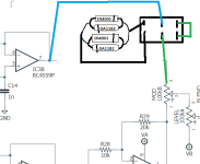
I tried adding a toggleswitch with diodes between IC3 pin 6 and 7, but i couldn't hear any change. I guess i would need to lift that pin 6 out of its socket, but i'm not comfortable with this.

So i lifted the MOD pot leg 3 instead, and wired the switch to IC3 pin7 and MOD leg 3, that way it worked.

I tried a weird diode combination from a DS1 mod project, found in my diode box :

1759958609006.png
and later a pair of 5mm red diodes set in antiparallel, but i didn't like the compressed sound texture in both cases.

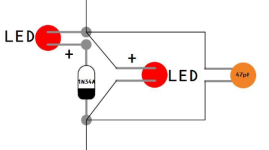
Finally i tried another weird diode setup from another project that i cant remember, and decided to keep it, for now.
There are silicon and germanium diodes, probably combined to get some specific forward voltages.

The compression texture is smoother than leds and yet still effective to soften the raw distortion a little around the edges. Noticeable but not too much.
1759962519228.png


Drilled a new hole in the enclosure near the 3PDT for the extra switch. As planned, the diodes arent affecting the "filtered and refined" distortion channel.
 
Last edited:
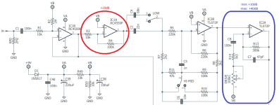
Gain comes from these 2 stages:
1759977476200.png

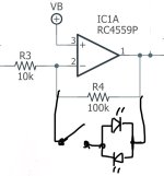
For the IC1A stage, I would use 2 LEDS in parallel (with opposed polarities) on the R4 (is an inverter opamp stage, so is hard clipping, even in the feedback loop),

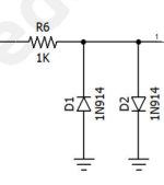
And for the IC2A stage, I would add a current limiter resistor to the output and use 2 LEDS on the output to VB, similar to this:
1759977828964.png (BE SURE TO CONNECT THEM TO VB, NOT GROUND!)

If the current limiting resistor will be always on the circuit, i would make it smaller to avoid it affecting the following filters. 220 or 100 ohm maybe.

Also, if you are going to connect it to a switch, a very nice option is to have asymetric clipping, specially on the first stage (a LED and a 1N4148 would work great).
 
Oh ? so that's not the 1rst or 2nd distortion path ? IC3a and IC3b and their surrounding parts aren't gain stages ?

I thought these were the 2 distortion's channels , and the mod control pans between both paths:
View attachment 103250

Build docs mention "the signal is split into two paths". If i'm wrong can you please help me figure out what are those 2 paths ?
The 2 modes are EQ related (just filters), not gain/distortion related.
 
The 2 modes are EQ related (just filters), not gain/distortion related.
Thanks for your suggestions !

I would be curious to hear the results of these changes, but with 5 extra parts i wouldn't be able to switch back to the stock version.
There isn't much room left in the enclosure, not enough for some big toggleswitch.

I guess i could leave the first pair of diodes permanently in the circuit and only put the last diodes on a DPDT switch.
Can you tell which diodes will have the most noticeable impact on the signal, those at IC1 or those at IC2 ?

It looks like your diode clipping mod would affect both distortion channels, but it happens before the tone shaping section so this could still be interesting to try at some point.
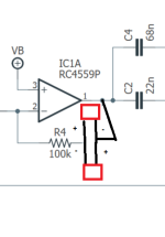
For the IC1A stage, I would use 2 LEDS in parallel (with opposed polarities) on the R4

like this, desoldering one R4 leg to connect these leds ?
1760009410954.png

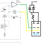
and for the IC2A stage, I would add a current limiter resistor to the output and use 2 LEDS on the output to VB
If the current limiting resistor will be always on the circuit, i would make it smaller to avoid it affecting the following filters. 220 or 100 ohm maybe.
I guess i could easily add this limiter resistor to the diodes on a DPDT switch, i could also use a trimmer to dial the right value, but im not sure
what value i would be looking for. What is the purpose of this current limiter resistor ? How can we figure out the optimal value ?

I would also probably need to lift a part to connect a switch with diodes after IC2A stage. If i lift IC2 pin1 out of the socket and wire the switch between this pin1 and R13 pad, would it work ?
1760012577226.png
 
Last edited:
Thanks for your suggestions !

I would be curious to hear the results of these changes, but with 5 extra parts i wouldn't be able to switch back to the stock version.
There isn't much room left in the enclosure, not enough for some big toggleswitch.

I guess i could leave the first pair of diodes permanently in the circuit and only put the last diodes on a DPDT switch.
Can you tell which diodes will have the most noticeable impact on the signal, those at IC1 or those at IC2 ?

It looks like your diode clipping mod would affect both distortion channels, but it happens before the tone shaping section so this could still be interesting to try at some point.


like this, desoldering one R4 leg to connect these leds ?
View attachment 104243


I guess i could easily add this limiter resistor to the diodes on a DPDT switch, i could also use a trimmer to dial the right value, but im not sure
what value i would be looking for. What is the purpose of this current limiter resistor ? How can we figure out the optimal value ?

I would also probably need to lift a part to connect a switch with diodes after IC2A stage. If i lift IC2 pin1 out of the socket and wire the switch between this pin1 and R13 pad, would it work ?
View attachment 104249
The first one should be more like this for traditional clipping:
1760044328445.jpeg
 
The most difference will be the ones on IC2A. The last stage.

For the first one, you can just ignore the switch. Give a chance to asymmetric clipping, it will give more natural dynamic response (softer transition from clean to clipping)
 
Back
Top