Chuck D. Bones
Circuit Wizard
It's a two-fer this week!
This is the first Death By Audio circuit I've breadboarded. I've always thought their stuff was a little "out there" and this one is no exception. Before I built the breadboard, I listened to a demo on YaoTaob. Sounds pretty good. Definitely worth investigating.
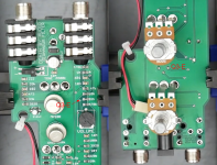
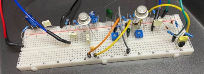
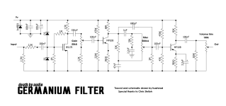
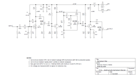
The first schematic is one I found on the web. It will sounds like ass if you build it per that schematic because the biasing will be all wrong. In the production pedals, Q2 and Q3 are installed backwards (emitter & collector swapped) in traditional DBA style. There is a tear-down video on YT and if you can get past the incessant blabbing, the guy flips the board over at 8:09 and the trained eye can spot a trace that confirms E & C Are reversed on at least one of the Ge transistors. I ran some sims, and then built my breadboard per the schematic below, with the correct orientation for Q2 & Q3. I also changed the reverse power protection to a series diode and replaced the Volume Trim with a pot with a knob. I deleted the superfluous 1M resistor between pin 2 of the FILTER pot & GND and subbed in a pair of randomly selected MP38A transistors for Q2 & Q3. The production pedal's audio path is faithfully reproduced on the breadboard. I did not need to tweak the bias.
Feedback thru R3 causes the input impedance to be fairly low, around 25K. This makes the circuit very responsive to the guitar's knobs. D1 & D2 provide overvoltage and ESD protection for Q1.


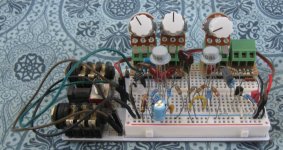
Knobs (L-R): LEVEL - FILTER - GAIN
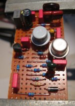
Q1 on the far right, Q3 on the left.

The FILTER knob is something else! Large range of tones. This is the end-to-end freq response with GAIN at 5 (noon) and FILTER at 0 (green), 5 (blue) & 10 (red). Below noon, the tone becomes fat and at zero is thick & heavy. Around noon, the tone is balanced and clear. Above noon, it gets bright and thins out at 10. DBA really nailed the EQ circuit.

This is the first Death By Audio circuit I've breadboarded. I've always thought their stuff was a little "out there" and this one is no exception. Before I built the breadboard, I listened to a demo on YaoTaob. Sounds pretty good. Definitely worth investigating.
The first schematic is one I found on the web. It will sounds like ass if you build it per that schematic because the biasing will be all wrong. In the production pedals, Q2 and Q3 are installed backwards (emitter & collector swapped) in traditional DBA style. There is a tear-down video on YT and if you can get past the incessant blabbing, the guy flips the board over at 8:09 and the trained eye can spot a trace that confirms E & C Are reversed on at least one of the Ge transistors. I ran some sims, and then built my breadboard per the schematic below, with the correct orientation for Q2 & Q3. I also changed the reverse power protection to a series diode and replaced the Volume Trim with a pot with a knob. I deleted the superfluous 1M resistor between pin 2 of the FILTER pot & GND and subbed in a pair of randomly selected MP38A transistors for Q2 & Q3. The production pedal's audio path is faithfully reproduced on the breadboard. I did not need to tweak the bias.
Feedback thru R3 causes the input impedance to be fairly low, around 25K. This makes the circuit very responsive to the guitar's knobs. D1 & D2 provide overvoltage and ESD protection for Q1.
Knobs (L-R): LEVEL - FILTER - GAIN
Q1 on the far right, Q3 on the left.
The FILTER knob is something else! Large range of tones. This is the end-to-end freq response with GAIN at 5 (noon) and FILTER at 0 (green), 5 (blue) & 10 (red). Below noon, the tone becomes fat and at zero is thick & heavy. Around noon, the tone is balanced and clear. Above noon, it gets bright and thins out at 10. DBA really nailed the EQ circuit.


