New and improved circuit, any criticism appreciated

BuddyBoy122008

New member
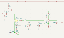
This is the second version of a circuit I've been working on. I took suggestions from here and implemented them as best I could. I'm looking for more criticism on my layout, values, etc. And I would also enjoy help with what to add to the circuit to be ready for the pcb stage (after I breadboard ofc ;)).
 

Attachments

  • Screenshot 2025-12-05 160238.png
    Screenshot 2025-12-05 160238.png
    20.4 KB · Views: 37
you won’t have much gain. Bring R4 down a lot, like 10k or even lower. Experiment with C3 for the bass cut, probably in the 22n to 100n range depending on what R you use.

The BM tone circuit cuts a lot of volume. You may find you want an extra gains stage, either op amp (since you have an unused half of a dual op amp, or you transistor (like the big muff has).

Could use an on-off-on switch for the hard clipping diodes. If the 4148s are on, you won’t hear the leds since the threshold is higher.

Every pedal circuit I’ve ever seen has a Cap from 9v to Gnd. (100uf commonly). The series 1n5817 is standard in all pedalpcb boards and I’ve adopted it for anything I make.
 
I don't think those LED clippers will do much of anything if you're feeding a normal guitar signal into the op amp. The diodes in the feedback loop of the op amp in conjunction with the comparatively small guitar signal will be limiting the maximum achievable output voltage swing too much, regardless of how high you set the op amp gain, so the LEDs will barely turn on if at all. I'd experiment with putting another gain stage either before or after the op amp to make those hard clippers work a little harder, otherwise there won't be much distortion really even with the 4148 hard clippers. And as has been said already, overall output level will be quite low due to the insertion loss of the tone stack.
 
I don't think those LED clippers will do much of anything if you're feeding a normal guitar signal into the op amp. The diodes in the feedback loop of the op amp in conjunction with the comparatively small guitar signal will be limiting the maximum achievable output voltage swing too much, regardless of how high you set the op amp gain, so the LEDs will barely turn on if at all. I'd experiment with putting another gain stage either before or after the op amp to make those hard clippers work a little harder, otherwise there won't be much distortion really even with the 4148 hard clippers. And as has been said already, overall output level will be quite low due to the insertion loss of the tone stack.
I agree with you.
 
Maybe move LEDs to feedback loop. If you want two hard clippers in series (which is an interesting idea), add a resistor between them. Specifically place it between SW1 and SW2. Place the lower Vf diodes after the higher ones.

Lower the vmid voltage divider resistances. On the order of 10k each or below.

Sometimes there is a small pF cap to GND before the signal hits the opamp. Worth consideration. Also spice model or breadboard with C2 in the fb loop. This can reduce treble as drive is increased, which is often desirable.

I would second those suggesting adding a cap from 9v to GND, adding another buffer following the volume control and adding a 1n5817 to the supply.
 
Back
Top