School me on C and W tapers behavior

RhPf Electronics

Well-known member
I am trying to find the best fit for a potentiometer within my circuit, but really, in simulation I only ever use A and B taper... I never really understood how the others work...

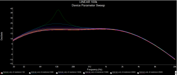
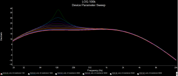
Here are the graphs with both tapers; I am greedy and looking for a more precise transistion on the early course of the pot, like "extra" log...
Basically; the lower the resistance, the louder the hump at 130Hz
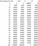
Can anyone give me a clue on what each value would look like for C and W tapers? table at the end is what ChatGPT told me they behave like for a 100k pot, not sure this sounds correct...


1732378619567.png
1732378639147.png


1732379370478.png
 
It’s easier to show graphically. C tapers are the opposite of A tapers, where the resistance increases quickly then slows down as you turn clockwise. K tapers are a hybrid of linear and logarithmic(?) where half the sweep mimics one taper then switches to the other. Any taper pot will work in any given circuit as long as the value is correct. The difference is how it behaves as you turn it. Some linear pots don’t do much until the last quarter turn. C tapers would be a good substitution there.

 
Ok, so confirmation on what I showed on the table for C taper, which makes the graph look like this, exactly the opposite of what I'd love:
Has anyone ever managed to simulate an "extra" log taper? I tried several combinations with different tapers and resistors in parallel but this just makes it worse....
1732381684564.png
 
1732419351199.png
1) is your standard linear "B" taper,
2) is your standard logarithmic or "audio" "A" taper (which is ironic because that curve is not a logarithmic function),
4) is the reverse-log or "C" taper (which is really more like a logarithmic function),
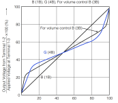
5) is a "W" taper, sort of sigmoidal where you have a reverse-log taper from 0-50 and a log taper from 50-100.
 
These graphs are straight outta the Alpha datasheet.

A-taper is otherwise known as log or audio taper. Yes, as drawn they look more like an exponential curve, which is the inverse of log. It's not a true log (or exponential) curve; it is an approximation. It's basically linear from 0% to 50% rotation, and a steeper linear slope from 60% to 100% rotation with a smooth-ish transition from one slope to the other. This is simply how they make pots. The A-taper pots we buy from Small Bear, Stomp Box Parts, Tayda, etc. are 15% taper, which means at 50% rotation, the divider ratio is 15%. "Vintage" guitar pots are more like 25% or 30% taper. Fender uses various tapers in their amplifiers, as noted on the factory schematics. Note that the vertical axis is resistance divider ratio. Not resistance ratio.

1742913169732.png

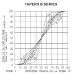
Alpha calls this next graph "B series." It includes B-taper and W-taper. W-taper is marked "4B(W)."

1742913693451.png
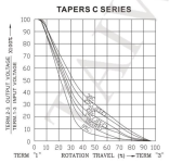
Here's C-Taper. It's a mirror-image of A-taper. Again, the pots we buy for pedals are 15% taper.

1742914727840.png
For simulations, I used these plots to create piece-wise approximations of the various tapers.

A-taper:
.step param A list 0 0.03 0.06 0.09 0.12 0.15 0.32 0.49 0.66 0.83 1

C-taper:
.step param C list 0 0.17 0.37 0.51 0.68 0.85 0.88 0.91 0.94 0.97 1

W-taper:
.step param W list 0 0.015 0.03 0.10 0.25 0.50 0.75 0.90 0.97 0.985 1.00

I then use the params to scale the two halves of a potentiometer.

{100K*A+1}
and
{100K*(1-A)+1}

It's not super accurate, bit it's close enough for Rock & Roll.
 
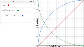
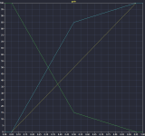
Necroing because I'm kinda in the same boat. I'm trying to simulate a pedal that uses a C taper pot for one of its knobs. I want to make a function based potentiometer model for LTspice and I find conflicting information everywhere (including this thread), regarding how the mythical C taper is supposed to look like. Some say it looks like the blue line. Some others say it's like the green line (wouldn't that basically be an A taper pot with the outer lugs reversed?).

Tapers Desmos Graphing Calculator.png

Red line is what a linear taper would look like for comparison purposes. I hope I find some definite answers here.
 
Last edited:
C taper is a reverse audio, or anti log. It's what you would get if you took a mirror image of an A taper.

To put it another way, if you wanted an A taper but wanted the knob to turn the other way around, use a C taper and switch the wires going to lugs 1 and 3.
 
MetalHeart, The answers to your questions are all in post #5, but I'll repeat it for you here.

The most accurate way to simulate non-linear taper pots in SPICE is the piecewise linear method using a .step param list statement.

Find a pot taper graph on the internet like this one from the Alpha datasheet. The C-taper pots we buy follow the 15C curve. The "15" indicates that at 50% rotation, the resistance ratio is 15% away from one end. In the case of reverse-audio (C taper), we are 15% away from the CW end of rotation. Now, read out the approx resistance ratio for each 10% of travel and enter it into a .step param list statement. You get this:

.step param F list 0 0.17 0.37 0.51 0.68 0.85 0.88 0.91 0.94 0.97 1

Where F is % resistance ratio variable.

1792075930192.png
 
Last edited:
Thanks to both of you for confirming. So if I understand correctly, C taper is just A taper with pin 1 and 3 locations reversed , right?
0.an8jz8aqb87PotentiometerSymbolSchematic.jpg
 
Last edited:
Thanks for clarifying. I only have one final question now.. Now that we know that the C taper resistance curve kinda looks like the green line from my graph above, does a taper that resembles the blue line exist commercially? And if it exists what is it called? (Also why is there so much misinformation out there from people on the internet saying the reverse/negative log pot curve looks like the blue line?)
 
Necroing because I'm kinda in the same boat. I'm trying to simulate a pedal that uses a C taper pot for one of its knobs. I want to make a function based potentiometer model for LTspice and I find conflicting information everywhere (including this thread), regarding how the mythical C taper is supposed to look like. Some say it looks like the blue line. Some others say it's like the green line (wouldn't that basically be an A taper pot with the outer lugs reversed?).

View attachment 126172

Red line is what a linear taper would look like for comparison purposes. I hope I find some definite answers here.
Blue is what a C taper looks like if you measure between lugs 1 and 2. Green is what a C taper looks like if you measure between lugs 2 and 3. Just two different ways of looking at it.

Note how if you take the sum of the blue and green plots at any point it adds up to 100%
 
Blue is what a C taper looks like if you measure between lugs 1 and 2. Green is what a C taper looks like if you measure between lugs 2 and 3. Just two different ways of looking at it.

Note how if you take the sum of the blue and green plots at any point it adds up to 100%
Thanks for the reply, you are right on that. I just did a test for my model reversing the outer lugs each time:

1792110446600.png

So for the Alpha datasheet curves @Chuck D. Bones posted above, resistance is measured between lugs 2 and 3, while the wiper starts from the fully left position(wiper position closest to lug 1)?
 
Last edited:
Thanks for the reply, you are right on that. I just did a test for my model reversing the outer lugs each time:

View attachment 126210

So for the Alpha datasheet curves @Chuck D. Bones posted above, resistance is measured between lugs 2 and 3, while the wiper starts from the fully left position(wiper position closest to lug 1)?
For the C-series chart yes. Since that’s how they’d most commonly be used. For all other taper charts it’s between lugs 1 and 2, but still measuring from the wiper fully counterclockwise/left to fully clockwise/right.
 
For the C-series chart yes. Since that’s how they’d most commonly be used. For all other taper charts it’s between lugs 1 and 2, but still measuring from the wiper fully counterclockwise/left to fully clockwise/right.
I guess that was the source of all my confusion. Many thanks for clearing things up to me 🙏

Edit: Looking back again the answer was in front of me the whole time... The Alpha datasheet curve graphs say which terminals are measured on the left side, my bad...
 
Last edited:
Thanks for clarifying. I only have one final question now.. Now that we know that the C taper resistance curve kinda looks like the green line from my graph above, does a taper that resembles the blue line exist commercially? And if it exists what is it called? (Also why is there so much misinformation out there from people on the internet saying the reverse/negative log pot curve looks like the blue line?)
Misinformation on the Internet? Surely you're joking.
 
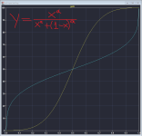
Hello again, so after finally understanding and making a C taper model I decided to review my W taper model because the same inversion can happen. Some time ago I came up with a pretty accurate sigmoid function-based W taper pot model for simulations (you guys are free to use it if you want) . But I am unsure about which of these curves below would best describe a tone pot found in a tube screamer. Good thing is I can simulate both with the same function, so no additional work needed here! I just need to know which to use!

LTspice_BlclIpp7jn.png


Again I find different opinions on the W taper and also the specific W taper pot the tube screamer uses:

(https://www.diystompboxes.com/smfforum/index.php?topic=251.msg1664#msg1664)
"~10% resistance at 30% rotation and ~90% resistance at 70% rotation." matches the Alpha datasheet (log to mid-point - anti-log after mid-point, more control at the extremes), but...
1742913693451.png
...according to Electrosmash it's the inverse: (anti-log to mid-point - log after mid-point, more control in the middle)
(https://electrosmash.mas-effects.com/tube-screamer-analysis.html#tone)
g-potentiometer.png
Does anyone have any insight on which one the tube screamer and other similar pedals use?
 
The plots in the "Tapers B Series" chart are "smoothed." Real pots are made from linear segments and the knees are not as smooth.

Ibanez's TS808 schematic shows G20K for the tone pot. The Kanengomibako trace of the TS9 shows W20K.

Electrosmash is not always correct. It's mostly good, but I have found incorrect and oversimplified analyses there. Do your own research. Get some pots and measure them.
 
Back
Top