This Week on the Breadboard: The Runoff Groove Umble

Chuck D. Bones

Circuit Wizard
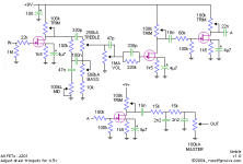
Lotsa good circuits on the Runoff Groove website. Here's another one, the "Umble." There's a good circuit description at Runoff Groove, so I won't repeat it here. I made a few minor tweaks. I used J210's, which have a higher Vp and Idss than J201s. To achieve the desired bias, I changed all of the drain trimmers to 10K fixed resistors and all source resistors to 3.3K. I selected four J210s that produced drain voltages between 5.0V and 5.5V. I installed a 1K gain trimmer between the 1st stage 4.7uF cap and GND so I could dial the gain down just enough so that the 1st stage would run clean with humbuckers. The resistance ended up around 300Ω. I inserted a 22K resistor between pin 1 of the GAIN pot and GND so that when GAIN is at zero, we still get some sound thru. I changed the BASS pot to A250K and the MID pot to A50K because almost nothing happens above 250K or 50K, respectively. Just about any JFET will work here if we adjust the source & drain resistors accordingly. The J210s produce slightly more gain than J201s and have a bit more headroom. The tone knobs, particularly MID, have a different feel from the standard Fender tone stack. Very smooth tone over the entire GAIN range. Highly recommended.

ROG Umble.png

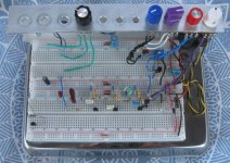
The 1st stage is upper right. 2nd stage is lower right. 3rd & 4th stages at the middle of the breadboard.
Knobs (L-R): VOLUME - BASS - MID - TREBLE - GAIN.
ROG Umble cb mod v0.1 breadboard 02.jpg
 
So is it the tone stack that makes the Dumble, do you think? Does the circuit actually resemble a dumble in tone? I had read that article at one point. I love runoffgroove!
 
It's safe to say that everything Mr. Dumble did in those amps contributed to special tone. The tone stack is but one small part of it. This pedal was inspired by the elusive Dumble tone. It does not pretend to reproduce said tone. Dumble amps are bespoke and everyone is going to sound different to some degree.

Some people might like this circuit better if had the classic Fender or Marshall tone stack. The most important thing about the tone stack in this circuit is where it's placed: before the distortion stages. That allows us to tailor what goes into the distortion stages.
 
  • This ROCKS!
Reactions: gtt
The other thing I didn't pick up on right away then did when I looked at the article and your circuit again is that the source bypass of those JFETs is putting the corner around the low E note or so, and it's on every JFET, so it's cumulative. Presumably to roll off enough bass to tighten the distortion. I also see that 330p bypass on the gate resistor after the tone stack. A little sparkle before the distortion? And then relatively aggressively roll off at the end to smooth it out. Very interesting. This seems like a circuit that would sound good biased at a higher voltage like 18v?
 
I built one of these many moons ago on a home etched board to Runoffgroove specs.
The pedal is long gone to a friend who loved it. I liked it too, I thought it had a bit too much gain from my memory, I used the gain mainly up to halfway. Also thought that it was a bit noisy with higher gain.
Maybe I should revisit it on a fabbed pcb and with lowered gain for my taste.
 
Each stage's source bypass rolls off the bottom end below 67Hz. That by itself is not enough to tighten the bottom end much. The tone stack does all of the heavy lifting.

The 330pF in parallel with the 220K resistor is there to more-or-less compensate for the JFETs input capacitance. In this circuit, it's enough to add a fair amount of brightness.

The double passive low-pass filter at the end (2 ea 15K & 2.2nF) forms a simple cab sim that shows up in a number of pedals. It has a gentle roll-off starting at 2.8KHz.

18V power will increase the headroom and available volume. Whether that achieves the desired tone is in the ears of the player. This circuit is supposed to distort. Raising the rail voltage reduces distortion, all other things being equal.
 
I built one of these many moons ago on a home etched board to Runoffgroove specs.
The pedal is long gone to a friend who loved it. I liked it too, I thought it had a bit too much gain from my memory, I used the gain mainly up to halfway. Also thought that it was a bit noisy with higher gain.
Maybe I should revisit it on a fabbed pcb and with lowered gain for my taste.
One could reduce the gain at each stage with a small resistor in series with the 4.7uF cap. Or simply remove one of the stages.

My breadboard is not noisy per se, but it is good at amplifying any noise and hum coming from the guitar and cable. I use quality parts, which I know you do too.
 
  • Like
Reactions: gtt
Maybe I didn't have the jfets well dialed in back then, it was one of my early builds and not much clue.
Not that I know much better these days ...
 
  • Like
Reactions: gtt
Interesting! I have played with compression/sag circuits like that before. In my experience they don't do much. In fact, the circuit already does part of the job of modulating the JFET bias simply by overdriving the gate. When the gate-source diode conducts, current flows from gate to source which alters the DC charge on the coupling capacitor, the 10nF guy in the case of the 3rd stage. That in turn temporarily biases the stage colder (lower drain current) which reduces the gain.
 
Do the J210's require selecting for Vp and/or Idss like J201's? if you did any selection, what values did you select for?

I built the breadboard one stage at a time. Once I had the 1st stage built, I measured the drain voltage. I tried a bunch of different J210s until I got 4 that had a drain voltage between 5.0V and 5.5V. I went thru a couple dozen to get 4. If that hadn't worked out, I would have fiddled the source or drain resistor on the ones that were close. I got quite a few that were just under 5V and quite a few that were around 6V. So one way or another, I would have gotten there.

Is this 'final' or still tweaking?
LoL. Is it ever? But seriously, the only thing I'm trying now is alternate tone stacks, just to see if I find anything really good. I changed the tone stack to what's in the Mostortion by adding one cap and fiddling a few component values. But I'm plenty satisfied with the existing tone stack.

For anyone that wants a lower gain circuit, just omit the source bypass cap from the 3rd stage. One could even go so far as to omit the entire 3rd stage.

One more thing...
Just for S&G, I tried four random J201s with a 1.5K source resistor and a 50K trimpot on the drain. to get 5.25V on the drain, the trimpot was set between 20K and 30K. Just FYI. I would not use a 100K trimpot with J201s in this circuit.
 
Last edited:
Hmmmm. seems a bit much for a circuit this simple. I might be more inclined to try a passive James circuit. Something like the one in the Viceroy.

The Umble and Fender/Marshall circuits do enough IMHO. I think the Umble does it just a little better.
 
Back
Top