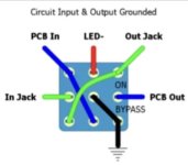
If I wanted to use the diagram below for my looper switch to completely ground input and output of the FX looped pedal (It’s an RC3 looper that introduces an annoying white noise when plugged that I can hear even when I have it looped using traditional 2DPT wiring), I have some questions;
I assume PCB in and PCB out are where I wire to my effect in and out?
Where would it be best to run the ground to? The ground/sleeve tab on one of the 4 jacks?
Do I still need to connect all 4 jacks via ground?
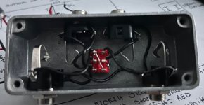
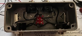
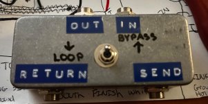
I also attached my first 2 versions I did where I could still hear the noise introduced from the pedal. I tried with a noisy germanium fuzz and it silenced it completely but the RC3 would not be silenced
I assume PCB in and PCB out are where I wire to my effect in and out?
Where would it be best to run the ground to? The ground/sleeve tab on one of the 4 jacks?
Do I still need to connect all 4 jacks via ground?
I also attached my first 2 versions I did where I could still hear the noise introduced from the pedal. I tried with a noisy germanium fuzz and it silenced it completely but the RC3 would not be silenced