Feral Feline
Well-known member
Inverting the phase was the thing I didn't want to do, I forgot it.
Thanks, but these layouts (I like vero!) are blend.
I don't want to blend fuzz and clean, there's no much sense to me turn the fuzz into clean. I want just add the clean in parallel, and I thought to have a slightly boosted clean, avoiding to get a signal too much weak comparing with the fuzz.
But if have the buffer in front I can't use a jfet boost.
Unless, I turn the buffer into a booster with less boost as possible.

But... You wouldn't "turn the fuzz into clean".

"But if have the buffer in front I can't use a jfet boost."
You can still have the JFET boost, but I think you'll need another inverting stage in the clean path so overall the clean doesn't invert.
Others have already made suggestions on various ways to accomplish exactly what you describe, getting a clean signal parallel to your dirt-signal. At some point the two signals will meet up somehow.
Your own schematics show the clean signal joining the dirt signal before final output. You have a volume on the clean and a volume on the dirt. Even though the clean was parallel to the dirt at one point, the two signals are joining together — This in itself is a "mix" or "blend" of the two signals at output.
To use the analogy of the glasses again, you've got two separate signals — two separate glasses, one is pure water the other is iced-tea (made by using the pure water
 ). The only way to have the liquids NOT blend-mix at some point is to have a friend drink one of the glasses — even then, down-stream they'll mix in the sewer.
SO, I really don't get your aversion to the terms "blending, mixing";
I guess I don't understand what you are trying to accomplish.

What am I missing, what am I not getting? Please explain further?
Cheers,

FF
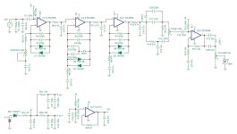
PS: for anyone interested, here's a perf of the Nucleon I drew up. Unverified.