ragamuffin
Well-known member
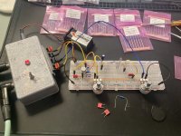
The past weak or so I've been watching/reading up on breadboarding and the Electra distortion circuit. Yesterday I breadboard the basic version (my first breadboard pedal) and then a modded version taking cues from JHS's "Shrieking Eel" Electra variant that he built on his youtube channel streams.
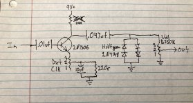
I got some NPN germanium transistors (2N1306 from Small Bear) and really like what they do in this circuit, they give it a gritty overdrive character even without the diodes, so I built the circuit around that! The one that I used tested at around 180hFE on my cheapo TC1 tester.
I didn't feel that I needed the "Body" control of the Shrieking Eel, which basically pans between a larger and smaller input cap, so I bypassed that and replaced it with a basic input cap and experimented with values, ending up with a .01uF cap.
I used a 50K trim pot to dial in the right resistance on R1 to get 4.5 volts which I decided was where I liked it, and replaced it with a resistor.
I played around with output cap value, but ended up with it back at .047uF cap like the Eel.
For the diodes I almost preferred it without them, but found a combination that I liked of "high voltage forward germanium diodes" from Small Bear in series with 1N4148s.
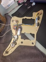
Anyways, it sounds really good! Nice gritty/low-gain-fuzz-ish overdrive tones! I think once I build it I'm going to install it in my jazzmaster in place of the Fuzz Face that is currently in there, since I also recently built a Sunflower/Sunface for my pedalboard.
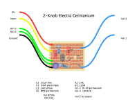
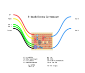
I created a stripboard layout for it in DIYLC layout creator: I'd appreciate it if anyone would look over it for any errors/issues!
Last edited:

