You are using an out of date browser. It may not display this or other websites correctly.
You should upgrade or use an alternative browser.
You should upgrade or use an alternative browser.
Diode bypass switch for Percolation Station
- Thread starter marksescon
- Start date

Chuck D. Bones
Circuit Wizard
I'm confused. Can you draw that on the schematic in the build docs?
Is the idea to disconnect the diodes?
Is the idea to disconnect the diodes?
marksescon
Active member
Sorry for delay in response.I'm confused. Can you draw that on the schematic in the build docs?
Is the idea to disconnect the diodes?
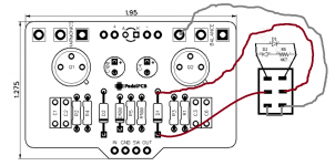
Yes, the idea is to disconnect ("lift"?) the diodes. Here is a picture of my wiring diagram:
Attachments
reubenreub
Active member
Yeah it's a lot easier using a DPDT switch for an added diode mod.Sorry for delay in response.
Yes, the idea is to disconnect ("lift"?) the diodes. Here is a picture of my wiring diagram:
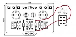
So since D1 already has its anode to ground and the cathode to signal (check the schematic) you don't need a wire going to a ground pad. Also it's called a diode "lift" because it's no longer connected to ground or is now "lifted" above ground. so you do nothing to the other side of the switch. So it kind of looks like this. If we're getting nitpicky you should also switch the red wires around to correspond with how you have the diodes connected there.
Alternatively you can use an on/off/on switch and put some other diodes on the other side, giving you normal diodes/lift/new diodes as your options.
Attachments
marksescon
Active member
Yeah it's a lot easier using a DPDT switch for an added diode mod.
So since D1 already has its anode to ground and the cathode to signal (check the schematic) you don't need a wire going to a ground pad. Also it's called a diode "lift" because it's no longer connected to ground or is now "lifted" above ground. so you do nothing to the other side of the switch. So it kind of looks like this. If we're getting nitpicky you should also switch the red wires around to correspond with how you have the diodes connected there.
Alternatively you can use an on/off/on switch and put some other diodes on the other side, giving you normal diodes/lift/new diodes as your options.
Thank you. I just completed my build and this works. I appreciate your response.
Chuck D. Bones
Circuit Wizard
I was gonna jump in but Reubenreub beat me to it. Good to hear you got it working.
JohnthePainter
New member
Supernoob here. Connecting to just D1 lifts both diodes? I’m thinking about maybe doing a diode lift switch on the new knight school fuzz.
Feral Feline
Well-known member
You'd move D2 off the board to the switch where D1 is, make sure they're anti-parallel (facing opposite ways).Supernoob here. Connecting to just D1 lifts both diodes? I’m thinking about maybe doing a diode lift switch on the new knight school fuzz.
Try my diagram shown in another thread here.