moosapotamus
Member
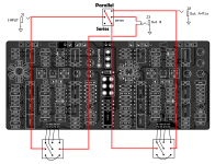
The Duo-Phase operates with the two phasers always in series. I'm thinking it would be cool to add a Series/Parallel switch. Something like this...

Seems kinda like a simplified version of the Phaser B input switch on the Mu-tron.
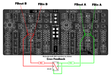
Moving on to add the dual inputs/outputs raised a few questions for me. Looking at the PPCB wiring diagram for two inputs / two outputs, it looks like you get the output of phaser A only from the first output and a series mix of both phasers from the second output. Am I seeing that correctly? Might be cool, instead, to have only phaser B in the second output.
Here's what I'm thinking...

With nothing plugged into either Out A or In B, the Series/Parallel switch works just like above. And I'm thinking that Out A should be a switching jack, just like the In B jack. Because If I am tapping Out A, I don't think I would still want Out A to continue on and mix with In B. I would want to have just phaser B at Out B. Switching to Parallel mode would do it, only phaser A at Out A and only phaser B at Out B. But then using Out A and In B with the switch in Series mode causes some minor inconveniences. Plug in to Out A and no input signal reaches In B. And using In B becomes just like bypassing Phaser A. But maybe that's just fine... Want to use the additional I/O jacks, switch to Parallel mode.
Does that make any sense? Any thoughts, concerns, or other ideas?
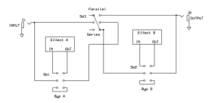
Seems kinda like a simplified version of the Phaser B input switch on the Mu-tron.
Moving on to add the dual inputs/outputs raised a few questions for me. Looking at the PPCB wiring diagram for two inputs / two outputs, it looks like you get the output of phaser A only from the first output and a series mix of both phasers from the second output. Am I seeing that correctly? Might be cool, instead, to have only phaser B in the second output.
Here's what I'm thinking...
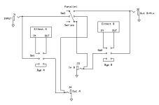
With nothing plugged into either Out A or In B, the Series/Parallel switch works just like above. And I'm thinking that Out A should be a switching jack, just like the In B jack. Because If I am tapping Out A, I don't think I would still want Out A to continue on and mix with In B. I would want to have just phaser B at Out B. Switching to Parallel mode would do it, only phaser A at Out A and only phaser B at Out B. But then using Out A and In B with the switch in Series mode causes some minor inconveniences. Plug in to Out A and no input signal reaches In B. And using In B becomes just like bypassing Phaser A. But maybe that's just fine... Want to use the additional I/O jacks, switch to Parallel mode.
Does that make any sense? Any thoughts, concerns, or other ideas?

