Emu Amp Sim Switch Mounting

almostjay

New member
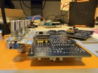
IMG_0003.jpeg Hi all. I am on my second try at building the Emu Amp Sim. I may have overreacted with my first build, but as it was coming together it did not seem like the switches were mounted correctly. It didn’t feel like they were high enough to protrude far enough above the base plate to access.

Anyway, before I solder in on round 2, I wanted to make sure I wasn’t missing anything obvious. I’ve attached a picture of the rough in. Is this how to mount the switches, or am I supposed to life the breakout board up on the header pins a bit so they sit higher?

Appreciate any advice!
 
That looks about right. The slide switch can touch the adapter board as long as the solder points don't touch the case of the switch (would cause a short). I assembled the adapter board, switch, and header pins as you have pictured here. However, the whole structure may need to be lifted off the main board a little bit so the top of the switch casing is at the same level as the top of the pots. I think it'd be best to have the board installed into a case or faceplate with the pots fastened to that, those header pins not yet soldered to the main board. That would help you line up everything before soldering. Worked well for me. For this and other builds, I always use either a drilled case or faceplate to line everything up including pots toggles etc before soldering any of those components.
 
That looks about right. The slide switch can touch the adapter board as long as the solder points don't touch the case of the switch (would cause a short). I assembled the adapter board, switch, and header pins as you have pictured here. However, the whole structure may need to be lifted off the main board a little bit so the top of the switch casing is at the same level as the top of the pots. I think it'd be best to have the board installed into a case or faceplate with the pots fastened to that, those header pins not yet soldered to the main board. That would help you line up everything before soldering. Worked well for me. For this and other builds, I always use either a drilled case or faceplate to line everything up including pots toggles etc before soldering any of those components.
Hey I appreciate this response. I definitely need to rough it in at the next level of assembly before soldering.

Next up is trying to drill the slots for the switches. I don’t have a good tool to do that but I figure I don’t have to be too clean since I have the faceplate.
 
The drill template suggests making a very large circular hole that would be mostly covered by the template. I've seen others drill a smaller hole then use a metal file to make it rectangular like the faceplate -- that's what I did. Aluminum is rather easy to file down.
 
Back
Top