Fried Seabed delay board help

Svenson007

Active member
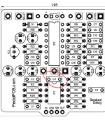
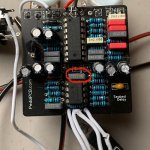
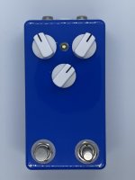
Hey guys. I build this seabed delay with a momentary oscillation stomp. I loved it but had a couple problems. I had to replace the 50kB repeats potentiometer. While doing this I burned the 22nf capacitor a bit. So I wanted to replace it. For some reason I just couldn’t not de solder it easily and ended up lifting the pads off the board. So basically I only have one repeat now. I’m wondering if anyone could help me find somewhere I could insert the 22nf cap into the circuit some other way. Doesn’t matter how ugly this is done haha. Thanks y’all.
 

Attachments

  • 948992E4-0454-4739-B12F-35B8AF74F6DF.jpeg
    948992E4-0454-4739-B12F-35B8AF74F6DF.jpeg
    339.3 KB · Views: 20
  • 3CE3CF28-53AB-4F59-9755-DAB40781D69A.jpeg
    3CE3CF28-53AB-4F59-9755-DAB40781D69A.jpeg
    106.8 KB · Views: 22
  • 4D2244EA-A288-40F2-B48A-40A0B1367D0F.jpeg
    4D2244EA-A288-40F2-B48A-40A0B1367D0F.jpeg
    840.9 KB · Views: 19
  • Like
Reactions: fig
Yes, you can jump from the input pad to R1. Oh wait, THAT 22nF...

R10 into the REPEATS pad
 
Last edited:
Yes, you can jump from the input pad to R1. Oh wait, THAT 22nF...

R10 into the REPEATS pad
Thanks man. I’m sorta dumb when it comes to visualizing. So basically a wire going from one side of the resistor to repeats pad? Thing is there isn’t really repeats pad because I fried them….
 
  • Like
Reactions: fig
Thanks man. I’m sorta dumb when it comes to visualizing. So basically a wire going from one side of the resistor to repeats pad? Thing is there isn’t really repeats pad because I fried them….
Wait. Maybe you mean the pad of the potentiometer? I’m confused haha.
 
  • Haha
Reactions: fig
Sorry, that was a bit vague. Someone please verify this;


View attachment 18828


BTW, The pedal looks great!
No worries! I appreciate the help. One thing I don’t get is the 22nf isn’t in the circuit due to the pads being lifted. The capacitor looks like it’s there but is doing nothing. So I don’t get how this is introducing it into the circuit? I probably didn’t explain this very well. Thanks for the compliment dude! I can build em… I’m just weak on the rest haha.
 
Last edited:
You'd solder one leg of the 22nF to the pot pin and the other to the pad with the 5K1 resistor. It may be easier to accomplish this on the underside of the board.

Here is the schematic showing the path and jump.

Screen Shot 2021-11-18 at 6.20.30 PM.png
 
Back
Top