Matopotato
Active member
Hi,
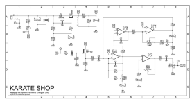
I was planning on building a copy of the Systech Hamronic Energizer and came across several implementations of it but using various different component values.
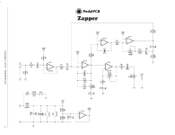
First the schematic from here at pedalpcb (https://docs.pedalpcb.com/project/Zapper.pdf)

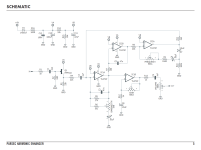
Then schematic from Aion FX, Parsec (https://aionfx.com/app/files/docs/parsec_documentation.pdf)

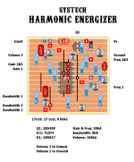
I also look at Dirtbox layouts (https://dirtboxlayouts.blogspot.com/2019/06/systech-harmonic-energizer.html)

My confusion is about a few differing values and choices, while some differences are probably more of protection, pull down resistor etc.
1. Zapper use 1M for pull down, while Parsec use 10M a bit further in?
2. Zapper use one TL072 op-amp as buffer (?) while Dirtbox and Parsec use a 2N5458 (which then has impact of surrounding Resistors, but that I assume is how each choice would dictate). What is the reason for using the TL072 here instead of what I guess is the original design?
Even if both methods "do the same thing", there was still a reason for the TL072 choice I suppose?
3. Zapper C2 (10uF electro) vs Parsec 1uF film box vs Dirtbox using 10uF electro but swapping the polarity as compared with Zapper?
4. Zapper using 10uF C102 in the voltage divider for Vref, vs Parsec using 47uF (C11)?
5. Zapper using IC 1.2 in the power section before Vref (Some buffer as well?)
6. Zapper output use C6 100nF and Volume pot A100k (as does Dirtbox) but Parsec has C9 1uF and A50k pot instead?
Perhaps no choice has any great impact on the final build, but I am always keen on learning and understanding why some choices ended up they way they did. Not asking to pick the designer's brain, but an overall understanding why one would make either choice in the end.
I was planning on building a copy of the Systech Hamronic Energizer and came across several implementations of it but using various different component values.
First the schematic from here at pedalpcb (https://docs.pedalpcb.com/project/Zapper.pdf)

Then schematic from Aion FX, Parsec (https://aionfx.com/app/files/docs/parsec_documentation.pdf)

I also look at Dirtbox layouts (https://dirtboxlayouts.blogspot.com/2019/06/systech-harmonic-energizer.html)

My confusion is about a few differing values and choices, while some differences are probably more of protection, pull down resistor etc.
1. Zapper use 1M for pull down, while Parsec use 10M a bit further in?
2. Zapper use one TL072 op-amp as buffer (?) while Dirtbox and Parsec use a 2N5458 (which then has impact of surrounding Resistors, but that I assume is how each choice would dictate). What is the reason for using the TL072 here instead of what I guess is the original design?
Even if both methods "do the same thing", there was still a reason for the TL072 choice I suppose?
3. Zapper C2 (10uF electro) vs Parsec 1uF film box vs Dirtbox using 10uF electro but swapping the polarity as compared with Zapper?
4. Zapper using 10uF C102 in the voltage divider for Vref, vs Parsec using 47uF (C11)?
5. Zapper using IC 1.2 in the power section before Vref (Some buffer as well?)
6. Zapper output use C6 100nF and Volume pot A100k (as does Dirtbox) but Parsec has C9 1uF and A50k pot instead?
Perhaps no choice has any great impact on the final build, but I am always keen on learning and understanding why some choices ended up they way they did. Not asking to pick the designer's brain, but an overall understanding why one would make either choice in the end.

