Chuck D. Bones
Circuit Wizard
It's been a minute. This time around, we'll discuss gain, bandwidth and slew-rate.
A typical opamp contains four functional blocks. The input stage, the gain stage, the output stage and the bias network. The input stage senses the difference between the the + and - inputs, amplifies that difference and sends it to the gain stage. The gain stage makes most of the voltage gain and drives the output stage. The output stage is typically a push-pull emitter-follower. Its purpose is to provide a low-impedance output and the ability to drive a feedback network and the next stage or device. The voltage gain of an emitter follower is close to unity, but there is a lot of current gain in the output stage. The bias network provides the various DC voltages and currents need to bias each stage. Opamps are intended to have a negative feedback loop around them which controls the DC operating point, gain and frequency response and minimizes distortion. With no feedback, the DC voltage gain of an opamp is very high, typically from 100,000x to a million or more. This is called the "open-loop gain." When we close a feedback loop around an opamp, then we get what's called "closed-loop gain." More on that in part 6. Opamps are designed to be stable under a wide variety of conditions and that is accomplished with something called "compensation." Basically, compensation reduces the open-loop gain at higher frequencies to prevent oscillation when feedback is applied.
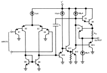
The schematic below shows the innards of an LM358 opamp. I chose that one because it is simple. The opamps we use contain a similar, albeit more complicated, circuit. Q1-Q4, Q8 & Q9 are the input stage. Q2 & Q3 form a differential amplifier. For small signals, the collector currents in Q2 & Q3 are proportional to the voltage difference between Q2-B & Q3-B. Q1 & Q4 are emitter-followers which increase the input impedance and reduce the DC input current. Q8 & Q9 form a "current mirror." What a current mirror does is it makes the current flowing into Q9 equal to the current flowing in to Q8. This converts the differential signal that opamp's input to a single-ended voltage at Q10's base. The diff amp & current mirror provide voltage gain in the neighborhood of 300x. Q10-Q12 form the voltage gain stage. Q10 & Q11 are emitter followers which prevent Q12 from loading the diff amp stage. Q12 is loaded by a current source (that circle with an arrow inside marked 100uA). This part of the circuit has a voltage gain around 1,000x. Notice Cc, that's the compensation capacitor. It's wrapped around the voltage gain stage and causes the gain to drop as frequency increases. Q5-Q7 & Q13 are the output stage. Q5, Q6 & Q13 are emitter-followers in a push-pull arrangement. Q7 provides short-circuit protection by killing the drive to Q5 if the current in Rsc gets too high.

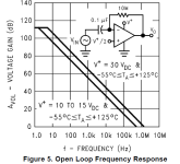
This next chart shows the open-loop gain vs. frequency. We're interested in the left-hand curve because it more-or-less reflects the conditions found in a guitar pedal. Notice that at DC, the gain is around 110dB (approx 300,000x). Also notice that the gain starts dropping off around 2Hz. The LM358's open-loop gain hits unity somewhere around 500KHz. This is not a good opamp to use in a high-gain application because at 10KHz, the open-loop gain is down to 34dB (50x). The term "bandwidth" describes the maximum frequencies we can pass thru a circuit. If we want 40dB gain with an LM358, the bandwidth is limited to 6 or 7KHz.

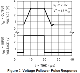
Last thing we will talk about is slew rate. Slew rate describes how quickly the output voltage can change and it is expressed in V/us. Some opamp datasheets specify slew rate, others do not. The LM358 datasheet does not specify a guaranteed slew-rate, but it does give us a clue of what to expect. This next chart shows the opamp slewing as fast as it can. The output voltage changes by 2.5V in 5us. That makes the slew rate 2.5/5 = 0.5V/us. What controls the slew rate? Two things: the maximum current capabilities of Q3 & Q9, and the value of Cc. When the output is slewing, Cc is being charged or discharged by Q3 or Q9. Their current is limited to 6uA by the current source above Q2 & Q3. In other words, 6uA is the most current Q3 or Q9 can put into, or take out of the bottom end of Cc. Making Cc smaller speeds up the slew rate, but at the risk of high-freq oscillations. See that squiggle in the trace around 25us? That's ringing and if it got much worse, the opamp could break into oscillation. Most opamps are internally compensated and we get what we get as far as slew rate and bandwidth go. A few opamps, like the LM308 and CA3130, have external compensation that lets us tailor the slew rate & bandwidth.

Next time: closed-loop gain, feedback and more about compensation.
A typical opamp contains four functional blocks. The input stage, the gain stage, the output stage and the bias network. The input stage senses the difference between the the + and - inputs, amplifies that difference and sends it to the gain stage. The gain stage makes most of the voltage gain and drives the output stage. The output stage is typically a push-pull emitter-follower. Its purpose is to provide a low-impedance output and the ability to drive a feedback network and the next stage or device. The voltage gain of an emitter follower is close to unity, but there is a lot of current gain in the output stage. The bias network provides the various DC voltages and currents need to bias each stage. Opamps are intended to have a negative feedback loop around them which controls the DC operating point, gain and frequency response and minimizes distortion. With no feedback, the DC voltage gain of an opamp is very high, typically from 100,000x to a million or more. This is called the "open-loop gain." When we close a feedback loop around an opamp, then we get what's called "closed-loop gain." More on that in part 6. Opamps are designed to be stable under a wide variety of conditions and that is accomplished with something called "compensation." Basically, compensation reduces the open-loop gain at higher frequencies to prevent oscillation when feedback is applied.
The schematic below shows the innards of an LM358 opamp. I chose that one because it is simple. The opamps we use contain a similar, albeit more complicated, circuit. Q1-Q4, Q8 & Q9 are the input stage. Q2 & Q3 form a differential amplifier. For small signals, the collector currents in Q2 & Q3 are proportional to the voltage difference between Q2-B & Q3-B. Q1 & Q4 are emitter-followers which increase the input impedance and reduce the DC input current. Q8 & Q9 form a "current mirror." What a current mirror does is it makes the current flowing into Q9 equal to the current flowing in to Q8. This converts the differential signal that opamp's input to a single-ended voltage at Q10's base. The diff amp & current mirror provide voltage gain in the neighborhood of 300x. Q10-Q12 form the voltage gain stage. Q10 & Q11 are emitter followers which prevent Q12 from loading the diff amp stage. Q12 is loaded by a current source (that circle with an arrow inside marked 100uA). This part of the circuit has a voltage gain around 1,000x. Notice Cc, that's the compensation capacitor. It's wrapped around the voltage gain stage and causes the gain to drop as frequency increases. Q5-Q7 & Q13 are the output stage. Q5, Q6 & Q13 are emitter-followers in a push-pull arrangement. Q7 provides short-circuit protection by killing the drive to Q5 if the current in Rsc gets too high.

This next chart shows the open-loop gain vs. frequency. We're interested in the left-hand curve because it more-or-less reflects the conditions found in a guitar pedal. Notice that at DC, the gain is around 110dB (approx 300,000x). Also notice that the gain starts dropping off around 2Hz. The LM358's open-loop gain hits unity somewhere around 500KHz. This is not a good opamp to use in a high-gain application because at 10KHz, the open-loop gain is down to 34dB (50x). The term "bandwidth" describes the maximum frequencies we can pass thru a circuit. If we want 40dB gain with an LM358, the bandwidth is limited to 6 or 7KHz.

Last thing we will talk about is slew rate. Slew rate describes how quickly the output voltage can change and it is expressed in V/us. Some opamp datasheets specify slew rate, others do not. The LM358 datasheet does not specify a guaranteed slew-rate, but it does give us a clue of what to expect. This next chart shows the opamp slewing as fast as it can. The output voltage changes by 2.5V in 5us. That makes the slew rate 2.5/5 = 0.5V/us. What controls the slew rate? Two things: the maximum current capabilities of Q3 & Q9, and the value of Cc. When the output is slewing, Cc is being charged or discharged by Q3 or Q9. Their current is limited to 6uA by the current source above Q2 & Q3. In other words, 6uA is the most current Q3 or Q9 can put into, or take out of the bottom end of Cc. Making Cc smaller speeds up the slew rate, but at the risk of high-freq oscillations. See that squiggle in the trace around 25us? That's ringing and if it got much worse, the opamp could break into oscillation. Most opamps are internally compensated and we get what we get as far as slew rate and bandwidth go. A few opamps, like the LM308 and CA3130, have external compensation that lets us tailor the slew rate & bandwidth.

Next time: closed-loop gain, feedback and more about compensation.
Last edited:
