Opinions sought on a BC capacitor hack..

DS13

Member
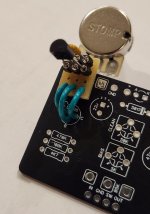
I have been tacking BC caps onto the back of boards, which works fine. However, I wish there was a utility / daughterboard for main boards that do not accommodate them - so the caps can be socketed along with the transistors they are paired with.

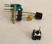
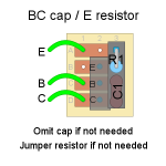
In trying to find a workaround, I came up with this - just a tiny piece of floating stripboard with sockets for the transistor and capacitor.

Has anyone done anything similar and/or see any concerns, or is this a solution in search of a problem?

BC cap hack.jpg
 
So simple and efficient idea. Gonna steal it to my imaginary toolbox if you don’t mind. :)

Taking it further, would cutting leaf contact socket to size work as straight to PCB -solution? Just if the mounting space is enough fir stuffing cap and transistor legs in.
 
Last edited:
OK, after a poor night's sleep I came up with a better way that is much smaller, uses less materials and takes less effort. Credit @Robert for spacing the transistor pin pads at .1".

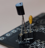
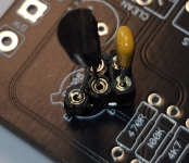
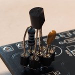
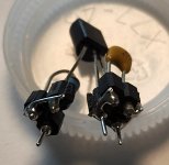
On this particular board, the transistor pins form a triangle, but the same would work for 3 pins in a line. All I did was take a 2-pin piece of socket, cut the pins and soldered the pin bases to another socket pair with pieces of scrap leads, providing the 2 parallel sockets for the transistor and BC cap. Then the full pins are soldered to the board as usual, along with the single emitter socket.

BC sockets 1.png BC sockets 3.png
BC sockets 4.png
 
Similarly, I realized I could hack some sockets for an optional emitter resistor (or jumper for 0R). I made the BC and E pieces separately so they can be used one only, or both together.

There are probably boards that don't have the real estate for this, but the stripboard method in the OP will always work for tighter spaces and can be similarly expanded for the emitter resistor with a 4th track.

Transistor Hack.png

As an aside, holding the 1 and 2 pin sockets together to bridge is a bitch, but I found that just inserting the pico cap in them orients them perfectly! Then secure it, stab a piece of scrap lead into a hunk of Blu Tack, stick it so the lead spans the pin bases and solder it up. The socket holding the resistor body goes to the emitter pad on the main board..

Emitter Resistor sockets 1.jpg

Emitter Resistor sockets 2.jpg
 
Last edited:
Back
Top