Right now I’m thinking of using the R2 pads as Send/Receive to a daughter board. On the daughter board I’ll have R2 and I guess some coupling caps? How do I determine what value caps to use? Any other pitfalls I need to be aware of?
The ultimate goal is to have a footswitchable “big” reverb in parallel with the Sproing.
I love ideas like this and have a few similar ideas I've yet to breadboard.
Try to find a similar circuit that already has done something comparable. For instance, the Spirit Box (EQD Ghost Echo) runs a delay and a reverb together while there's a dry signal as well.
Note how the Sproing's dry signal and the Spirit Box are very similar, but that the Spoing doesn't have a coupling-cap leading into its reverb section (the input cap having already taken care of blocking DC); but the Spirit Box has one cap (followed by a resistor) that leads into both the delay and reverb.
Compare that with the VFE Dragonhound (Madbean) schematic, which runs a Ratty and Screamerish coupla signals in paralleloland.
I'm thinking build the two circs separately, and just try inserting the BigVerb in at R2's pads like you said. It's in/out caps will take care of any DC — you might have to adjust R2 value, or the output value of the BigVerb.
Pitfalls...
Beware of Phase-Cancellation issues.
So long as your BigVerb doesn't invert phase, I think it'll be okay.
R2: Maybe install a 10k or 20k trimmer (or a 5k fixed resistor in series with a 10k trimmer instead of just the single 10k fixed resistor...
I did manage to give this a go on the breadboard today. It worked well! I think I’m going to have a TRS insert loop rather than build a second board into the same box, so I did add the coupling capacitors. I ended up using 4.7uF and a 100k pull-down after R2 for the send. I chose 4.7uF because that’s what the circuit uses on its output . I did get popping if I omitted the pull down.
On the return I used a 100nF coupling capacitor (again, like the input of the circuit). From my limited knowledge the input impedance would have been 39k going straight in to the mixing section, so I used the spare opamp to put a buffer in front.
Overall I’m really happy with it! The big verb stays very clear.
Now I’m starting to think about changing the switching to let the reverb tails spill over…
Thinking aloud, helps me solidify things in my own mind — please forgive...
Stock, R2's limiting the dry signal from the input buffer to the output buffer, keeping the dry signal in check and I imagine providing still close to unity gain.
The input signal goes into pin-3 of IC2 (first op-amp +), so it's phase is not inverted;
signal gets split and 1/2 goes on as dry through R2 and enters pin-5 of IC2 (2nd op-amp +) and once again is NOT inverted.
The other half of the split signal goes to IC4's inverting input (pin-2 -), now it's out of phase with the dry signal, and then gets 'verbed up by IC3 (Belton's brick) — if left as is it will cause phase cancellations. From the brick the wet signal goes back to IC2's 2nd op-amp pin-2 -, which inverts the signal so it's back in phase with the dry signal and thus the dry and wet can now be blended together with no cancellations.
Given all the hoops the wet signal has to jump through, I'm guessing there is some signal degradation/loss, which R2 will do the same for the dry signal.
R2 as an effects loop:
I'm betting you could go without an output cap, as most pedals plugged into the loop will have an input cap already performing the same role. Please remember that two caps in series reduces the overall capacitance whereas caps in parallel sum.
You could try removing the loop-out cap, but I think it's a good idea to keep it. Some JFET boosts and whatnot don't have an input cap. Hedge your bets.
I'm not familiar enough with calculating in/out impedances and of course the loop's will vary depending on what's plugged into it, so I think it was a good call with the values you chose — for myself, I'd bump the 100n return to 220n 'cause I'd use it with my bass instruments. How that affects the impedance, I've no idea.
Further to R2 as a variable resistor: If you've got a really hot signal coming back through the loop-return, having VR2 on the return-input will allow you to keep the hot signal of the pedal in the loop (a compressed high-gain distortion pedal, say, that won't sound good unless it stays cranked) but you don't want/like the sound of how that high-gainer in the loop is causing distortion in your op-amp buffer of the Sproing — trim that hot signal down to where you've got the sound you want at a level that won't further clip in the Sproing (and better match the Sproing's wet signal, as well).
Does that make sense?
Anybody with solid mathematical-knowledge of these sort of circuit manipulations want to chime in?
I'm all theoretical talk, though, Carpenter — you're the one actually breadboarding it and making things happen. Kudos!
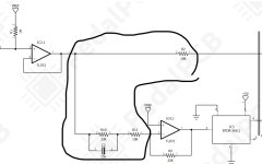
Ok that helps a lot, and I think you just triggered a lightbulb moment for me. Looking at the circled section, if R10 and C3 were jumpered, then the same amount of signal would flow through both R2 and R11.
However, R10 restricts some signal from passing through R11, while the parallel C3 allows some of the higher frequencies to pass. The result is that less of the low frequencies go through the wet path?
That being the case, we can’t use the circuit as I described for true parallel processing, as the dry path will be colored with a bit of a bass boost (compared to the wet signal).
Still really neat to fiddle with this on a breadboard though. It feels like magic.
See how complex and simple it can be? Pros & cons to all.
I think you've got enough with the existing circuitry and R2, and that you'll likely not hear much difference if any with a perfectly-matched split circ feeding the 2 reverbs.
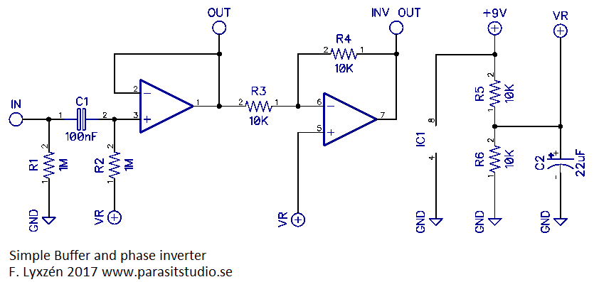
The only problem with making it a loop is if you get an inverting-phase pedal in there — you'll want a small buffer daughterboard on the loop-return that can flip phase with the flick of a toggle such as Parasit's...
 . I did get popping if I omitted the pull down.