Super-embarassing Rangefinder capacitor question

mkstewartesq

Well-known member
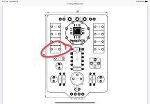
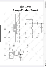
So I finally got around to building this kit, which was one of the first I bought back when I thought "uf" always meant electrolytic capacitor and "nf" always meant film box (didn't know yet that there was a conversion to be done between uf and nf, etc.). Long story short, slot C8 is 1uf, and I bought a 1uf electrolytic cap rather than a box cap, and I have no film box caps with that value/equivalent value in nf.. I understand that in a pinch an electrolytic cap can be used here (not ideal) but obviously polarity matters - and since this cap is between a rotary switch and the rest of the circuit, I have no idea which side should be positive and the relationship to/interplay with the rotary switch is a new one to me so I'm not sure how to read the schematic to solve for this one.

Can someone help, please, by letting me know by reference to the board layout where the positive lead should go on C8? Schematic and board layout attached.

Thank you.
 

Attachments

  • IMG_1423.png
    IMG_1423.png
    399 KB · Views: 13
  • IMG_1422.png
    IMG_1422.png
    667 KB · Views: 13
You have to orient the electrolytic cap so that the negative lead has continuity with the Base of Q1.
 
Thank you! (You have no idea how proud I am of myself that I didn't have to ask "how do I determine that?") Checked with a multimeter, and the left pad of C8 has continuity with the Base of Q1. Never would have figured that out myself.

For my own learning, do you mind explaining what you read/what someone smarter than me would look for in that schematic that gave you that information?

Thank you again! (Now I need to go see how poorly I purchased for all of these other kits I bought before I knew even the minimal amount I do now.)

Mike

No sweat.

Typically with PNP, or positive ground oriented transistor based effects, your polarized components will have, you guessed it, positive terminals to ground.

NPN is the opposite, i.e. negative terminals to ground.

Ground connections are easy to remember.

When you have components in the signal path, a good rule of thumb is that you want the signal to “hit” the end of the component that goes along with its circuit polarity:

NPN Input Cap = Signal -> -
PNP Input Cap = Signal -> +
 
Thank you again, Big Monk. I’ll fully admit that it’s going to take me a while to fully understand that, but it’s a far better thing than not to have a new piece of useful information to digest and eventually integrate into my internal knowledge base. So I really, really appreciate you taking the time to explain.

By the way, the pedal lives! It actually wasn’t making any sound at first, so I prayed over it for a while (tested continuity too, but mostly prayed). Decided to give it an alcohol bath to get rid of the flux and when I hooked it back up to my test platform, it worked. I suspect that, since it’s the first time I used my test platform, I probably just wasn’t hooking it up correctly (it’s a PedalPCB audition platform but the terminal blocks I bought seem to work a bit differently than most others I’ve seen). Ordinarily I would’ve just boxed it but it’s going on three weeks and I’m still waiting for my UV print from Tayda so bouncing baby pedal is just going to have to stay naked and strapped to the audition platform for the foreseeable future.

M
 
Back
Top