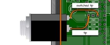
I don't know what else to tell you, Cybercow already pointed out the key in the lower right corner of the diagram he posted (which I've copied into the diagram below).
Right above that in Cybercow's diagram, it depicts the jack with pin numbers labelled.
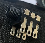
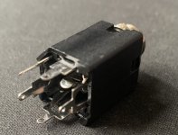
The stereo SWITCHING jack will work (but not a regular stereo jack), you just use the relevant pins you need: tip 5, sleeve-switch 3, and sleeve itself 1. Ignore the ring 2 and its associated switch pin 4. Here's PPCB's own WIKI diagram of the jack, to which I've amended the numbering.
View attachment 34439
Are you referring to SW1?
The following diagrams are from the Muzzle Classic build doc, but the same can be applied to the Muzzle SMD...
View attachment 34434
If you DON'T want R10 to be active, you don't have to do anything. No switch and no jumper required. You could even leave R10 off the board completely.
If you DO want R10 to be active, permanently, you would connect (jumper) SW1's pad 3 to pad 2.
View attachment 34435
For the sake of versatility, I'd just put in the SPDT on-on toggle for SW1 in the build.
OK, re-read the OP and had a peek at the other Muzzle build doc (I've got the Classic) If you're referring to the
SMD VERSION
and you're referring to
KEY1 and KEY2, then yes they are the outer two holes, the centre being ground and you've jumpered them correctly if going from one outer hole to the other — just make sure if you're using bare wire to jumper them that it doesn't touch the middle pad — better still, don't use bare wire.
View attachment 34437
Seems this isn't your
first rodeo with this circuit.
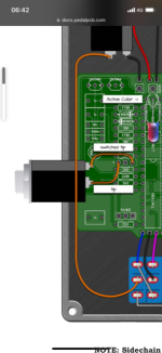
If you're building it without the side-chain key input jack, then you don't need to use a switched jack at all.
Just wire it up like a normal pedal with in-jack tip to the bypass-switch IN and the out-jack wired to the bypass-switch OUT (For bypass, I don't know if you're using a 3PDT handwired, a 3PDT with a daughterboard, or some type of relay-based bypass — otherwise I'd be more specific on the wiring).

")