Test Box Schematic - Am I understanding it correctly?

fav13andacdc

Active member
Hello, I ordered some parts to put together a Test Box using this page. https://tagboardeffects.blogspot.com/2014/09/test-box-20.html

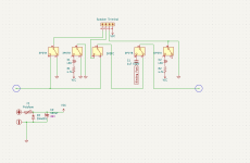
The wiring is a bit confusing so I put it into a schematic. Does this look accurate? I'm new to KiCad so I apologize if it isn't easily readable. I also added a Polyfuse in series with the voltage so I could safely use a 9v power supply. Is that the best option for protecting my power supply?

Overall just want to make sure I'm understanding the project correctly. Seems relatively straightforward.
Test.png
 
First off, this is a pretty straightforward project and also serves as a lesson in offboard wiring. I used the tagboard test box project as a guide when I did mine, but it was not a 1:1 clone. The purpose of the test box is to eliminate as may off-circuit items from potential troubleshooting (footswitch wiring, LED installation, audio jacks). It's a working pedal, but without the main circuit. The difference is that the main circuit is outside of the pedal and can be swapped out quickly (hence the speaker terminals ala tagboard). IN, OUT, 9V, and GND are the standard connections to a circuit. It also adds another element specifically for troubleshooting (audio probe). That is done replacing the OUT with a DMM probe and a coupling capacitor via a switch.

Unless you're confident in what you're doing, it's good practice to throw a polarity protection diode and a power filter cap in there just in case something bad gets plugged into it.

I'm mentioning this because I find the above schematic confusing and would rather think through the process logically.
Thanks for the response. Was hoping to hear from you as your project came up when I was researching. I apologize for the confusing schematic.

Please correct me if I'm wrong, but the purpose of each part protecting the power supply is:

Reverse polarity: Protects the circuit from incorrect polarity (duh)
Polyfuse: Protects the power supply in case of a short circuit.
Power filter cap: Prevents power supply hum.

It's a good idea to have all 3 of these for a test box, right? I'm thinking of the Auditorium(https://www.pedalpcb.com/product/pcb365/), which has a polyfuse. I also came across a Crowbar reverse polarity circuit which utilizes a polyfuse with a protection diode. Assuming adding the power filter cap would be a "mod" to this circuit. Just trying to avoid needing a battery every time I use the test box, while still getting the protection parts right.

As long as I understand those things, I have a good handle on the rest, despite my poor schematic layout skills, ha.
 
If the schematic makes perfect sense to you, by all means go for it. Some people need to write down the recipe before cooking. Others keep the recipe in their head. We all work differently.

If you're the only one who will be using the test box and you know exactly what you will be plugging into it, then there's no need for a protection diode or fuse. It's just good practice. Others here may disagree.
I took another stab at the schematic in an attempt to practice KiCad and improve my general understanding of schematic layouts. Any better?
1768321703797.png
 

Attachments

  • 1768321538565.png
    1768321538565.png
    34.4 KB · Views: 1
Makes sense to me. Your coupling cap for the audio probe doesn't need to be that big (1uf OR 630V). For guitar, a "standard" 100nf box cap will work just fine. If you've got the space you can use a 1uf box cap.
 
Back
Top