THAT2181 bypass: Threshold pot vs 750R path switching?
I'm trying to build a Decimator G String. I’ve looked at the schematics and gathered various information from the web. I even asked a previous question about the bypass method of this pedal. Eventually, I decided to follow the approach shared by Cybercow in this thread: https://forum.pedalpcb.com/threads/decimator-ii-g-string-vca-noise-gate.20155/.
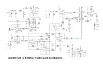
However, while reviewing the circuit, I have a concern about the switching method. As far as I know, the THAT2181 works with unity gain (0 dB) when the voltages at pin 2 (EC+) and pin 3 (EC–) are equal. In this noise gate circuit, it seems that switching at the Threshold pot’s pin 2 disconnects the control path, allowing the 2181 to act as a buffer—so when the pedal is off, it functions as a buffered bypass.
But in my view, simply disconnecting pin 2 of the Threshold pot might not completely isolate the input signal from affecting pin 2 of the 2181. Therefore, I'm considering whether it would be better to place the switching at the 750R resistor or the 1N5819 diode connected to the 2181. If that path is cut instead, the 2181 would only see the DC reference set by the 1M trimmer on pin 3, which makes me think it would behave more like a “true” unity buffer.

Of course, I plan to test this myself once the build is ready, but before I do, I wanted to ask: Does this idea make sense, and would it actually work as intended?
TLDR:
Instead of switching at the Threshold pot (pin 2), would it be better to switch at the 750R/1N5819 path so that the THAT2181 only sees the DC reference from the trimmer, effectively making it act as a cleaner unity buffer in bypass?
Thanks in advance for any insights!
I'm trying to build a Decimator G String. I’ve looked at the schematics and gathered various information from the web. I even asked a previous question about the bypass method of this pedal. Eventually, I decided to follow the approach shared by Cybercow in this thread: https://forum.pedalpcb.com/threads/decimator-ii-g-string-vca-noise-gate.20155/.
However, while reviewing the circuit, I have a concern about the switching method. As far as I know, the THAT2181 works with unity gain (0 dB) when the voltages at pin 2 (EC+) and pin 3 (EC–) are equal. In this noise gate circuit, it seems that switching at the Threshold pot’s pin 2 disconnects the control path, allowing the 2181 to act as a buffer—so when the pedal is off, it functions as a buffered bypass.
But in my view, simply disconnecting pin 2 of the Threshold pot might not completely isolate the input signal from affecting pin 2 of the 2181. Therefore, I'm considering whether it would be better to place the switching at the 750R resistor or the 1N5819 diode connected to the 2181. If that path is cut instead, the 2181 would only see the DC reference set by the 1M trimmer on pin 3, which makes me think it would behave more like a “true” unity buffer.

Of course, I plan to test this myself once the build is ready, but before I do, I wanted to ask: Does this idea make sense, and would it actually work as intended?
TLDR:
Instead of switching at the Threshold pot (pin 2), would it be better to switch at the 750R/1N5819 path so that the THAT2181 only sees the DC reference from the trimmer, effectively making it act as a cleaner unity buffer in bypass?
Thanks in advance for any insights!
