This Week on the Breadboard: Eric Mid Boost

Chuck D. Bones

Circuit Wizard
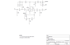
This is a minimalist version of the Clapton Mid Boost. Instead of discrete transistors, I used an opamp. There is only one knob: MID BOOST. The freq response is similar to the Clapton Mid Boost, with a broad focus on the mids. With the component values shown, the midrange is a little more focused than The Clapton when MID BOOST is dimed. The max gain and filter tuning are easily tweaked by adjusting C4, C5, R6 & R7. The Clapton Mid Boost is pretty stingy when it comes to current consumption, about 500μA. With the LM308H, this circuit consumes even less current, about 375μA. If you're not running this on batteries, then a TL071, LF351 or NE5534 would work well. Sounds great with single-coil pickups, fattens 'em up a bit.

Eric Mid Boost v1.2.png

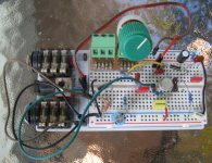
The two caps on the far upper right are spares for alternate filter tuning.
Eric v1.2 breadboard 02.jpg

Here's the freq response as the MID BOOST knob is turned.
Eric Mid Boost v1.2 freq resp.png
 
Last edited:
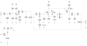
While studying this circuit, I noticed an interesting "feature." C5 & R7 provide a 7dB boost at 10KHz. I believe it is there to compensate for treble loss in the cable. This circuit was designed to be installed inside a Strat. 500pF to 1nF of cable capacitance between the guitar & amp (or pedal board) would be typical. So what happens if instead of putting this circuit in a guitar, we put it on a pedal board? Unless it's the last pedal in the chain (unlikely), it's going to sound brighter than the built-in-the-Strat circuit. We have a few options here.
1. Do nothing because we like the extra brightness.
2. Delete R7 & C5.
3. Add a 470pF cap from pin 2 of BOOST to GND to simulate the capacitance of a long cable.

In my circuit, R6 performs the same function. It limits how much of the high treble gets filtered out. See how the bottom green line rises 4dB on the freq response plot above? That's R6 raising the high treble in that circuit.

1761439742862.png
 
Mmmmmmaaaaaaybeeeeeeee. I'm going to experiment on my breadboard and see how different it sounds. It's only a few dB and it's at the top of the human hearing range, so we'll see.
 
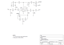
Here's the final version. I'm done with this. It sounds good but doesn't do anything that some of my other boost pedals do. From the previous rev, I increased R2 to add a little more bass and increased R6 for a little more brightness. One could put a switch in parallel with R6 to turn the brightness on and off. I like it on.

Eric Mid Boost v1.2.1.png
 
I'm built the original transistor version one month ago on veroboard, just the board. Probably I'll include the Aion three way switch to put in parallel to C5 (original schematic above) 6.8nF other caps, and maybe also a bass cut switch.
Very nice this op-amp version!
 
Haven't gotten there yet, but on the topic of op amps, you listed a few in regards to current usage, but I take it there's no strong leaning to internally or externally compensated guys? E.g. LM308 vs OP07
 
I have no preference for internally or externally compensated opamps in this (or most) circuits.
As long as the opamp has low enough noise & distortion and enough bandwidth to not trash the signal, then it's acceptable for a clean boost in my book. I simply chose the LM308 because it is low power and the original circuit was optimized for low power consumption. I could have just as easily built it with an OP07 or a TL071. Or a TL072 for that matter, but I have a personal aversion for installing a dual opamp when I know I'm only going to use half of it. BTW, TL061 is also low power.
 
Back
Top