You are using an out of date browser. It may not display this or other websites correctly.
You should upgrade or use an alternative browser.
You should upgrade or use an alternative browser.
Connecting Breakout Boards on Dual Switch Pedal?
- Thread starter apc42069
- Start date
Is that what your looking for ?
 wiki.pedalpcb.com
Check out the wiki page, there’s pretty much everything there.
2-in-1 Pedal Wiring - PedalPCB Wiki
Check out the wiki page, there’s pretty much everything there.
apc42069
Well-known member
Kinda/sorta. That diagram is the reason I’m thinking on jumping lugs 8 & 2.. but my switches already have breakout boards soldered on- so wondering if there’s a way to connect them without desoldering the boards off.Is that what your looking for ?
2-in-1 Pedal Wiring - PedalPCB Wiki
wiki.pedalpcb.com
Check out the wiki page, there’s pretty much everything there.
apc42069
Well-known member
Ok cool - thanks man!Find the lugs that correspond and run a jumper to them.
EDIT: You need to jump the Out on the one to the In on the other.
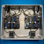
View attachment 27278
Wait actually, I feel like an idiot - sleep training my 6month old, have a heart lol.
Do I run a jumper from the pad of breakout board one (that typically runs to tip lug of out put jack) to the pad of breakout board two (that typically runs to tip lug of input jack)?
A picture is worth a 1000 words they say…Ok cool - thanks man!
Wait actually, I feel like an idiot - sleep training my 6month old, have a heart lol.
Do I run a jumper from the pad of breakout board one (that typically runs to tip lug of out put jack) to the pad of breakout board two (that typically runs to tip lug of input jack)?

Not my build, just did a search for you… send your thanks to @Danbieranowski ….
apc42069
Well-known member
Ahhhh hell yeah, thank you & thank you @Danbieranowski!!A picture is worth a 1000 words they say…
View attachment 27284
Not my build, just did a search for you… send your thanks to @Danbieranowski ….
I would have used one of my own build pictures. But I use an order switch to pick which FX goes first. All of it on a 4PDT switch to also activate a dual LED matching the FX LED letting me know which one is first. But that may have confused youAhhhh hell yeah, thank you & thank you @Danbieranowski!!

apc42069
Well-known member
It wouldn’t have not not confused me lol - I HAVE been wondering how this is done through.. so a preemptive thanks for when I eventually get there! What effects have you got wired up here?I would have used one of my own build pictures. But I use an order switch to pick which FX goes first. All of it on a 4PDT switch to also activate a dual LED matching the FX LED letting me know which one is first. But that may have confused you
View attachment 27285
This is Episode Boost and Dirty Sanchez OD. Please note that the order switching breaker board is a specific one. It fits on a 4PDT and leaves the 3 lugs on the right for the dual led. If you look carefully you’ll notice that I put a resistor attached to each of the dual LED leg. It’s in the red and green shrink wrap.It wouldn’t have not not confused me lol - I HAVE been wondering how this is done through.. so a preemptive thanks for when I eventually get there! What effects have you got wired up here?
